Subaru Impreza 3 / Impreza WRX / Impreza WRX STI. Service manual — part 238
EN(H4DOTC)(diag)-176
Diagnostic Procedure with Diagnostic Trouble Code (DTC)
ENGINE (DIAGNOSTICS)
AV:DTC P0202 INJECTOR #2
NOTE:
For the diagnostic procedure, refer to DTC P0201. <Ref. to EN(H4DOTC)(diag)-174, DTC P0201 INJECTOR
#1, Diagnostic Procedure with Diagnostic Trouble Code (DTC).>
AW:DTC P0203 INJECTOR #3
NOTE:
For the diagnostic procedure, refer to DTC P0201. <Ref. to EN(H4DOTC)(diag)-174, DTC P0201 INJECTOR
#1, Diagnostic Procedure with Diagnostic Trouble Code (DTC).>
AX:DTC P0204 INJECTOR #4
NOTE:
For the diagnostic procedure, refer to DTC P0201. <Ref. to EN(H4DOTC)(diag)-174, DTC P0201 INJECTOR
#1, Diagnostic Procedure with Diagnostic Trouble Code (DTC).>
6
CHECK FUEL INJECTOR OPERATION.
1) Connect all connectors.
2) Start the engine.
3) Check if the corresponding fuel injector
emits operating sound.
NOTE:
Use a sound scope to check the operating
sound.
Does the fuel injector emit
operating sound?
Even if DTC is
detected, the cir-
cuit has returned to
a normal condition
at this time. Repro-
duce the failure,
and then perform
the diagnosis
again.
NOTE:
In this case, tem-
porary poor con-
tact of connector,
temporary open or
short circuit of har-
ness may be the
cause.
Repair the poor
contact of fuel
injector connector.
Step
Check
Yes
No
EN(H4DOTC)(diag)-177
Diagnostic Procedure with Diagnostic Trouble Code (DTC)
ENGINE (DIAGNOSTICS)
AY:DTC P0222 THROTTLE/PEDAL POSITION SENSOR/SWITCH “B” CIRCUIT
LOW
DTC DETECTING CONDITION:
• Immediately at fault recognition
• GENERAL DESCRIPTION <Ref. to GD(H4DOTC)-102, DTC P0222 THROTTLE/PEDAL POSITION
SENSOR/SWITCH “B” CIRCUIT LOW, Diagnostic Trouble Code (DTC) Detecting Criteria.>
TROUBLE SYMPTOM:
• Improper idling
• Poor driving performance
• Engine stalls.
CAUTION:
After servicing or replacing faulty parts, perform Clear Memory Mode <Ref. to EN(H4DOTC)(diag)-63,
OPERATION, Clear Memory Mode.>, and Inspection Mode <Ref. to EN(H4DOTC)(diag)-49, PROCE-
EN(H4DOTC)(diag)-178
Diagnostic Procedure with Diagnostic Trouble Code (DTC)
ENGINE (DIAGNOSTICS)
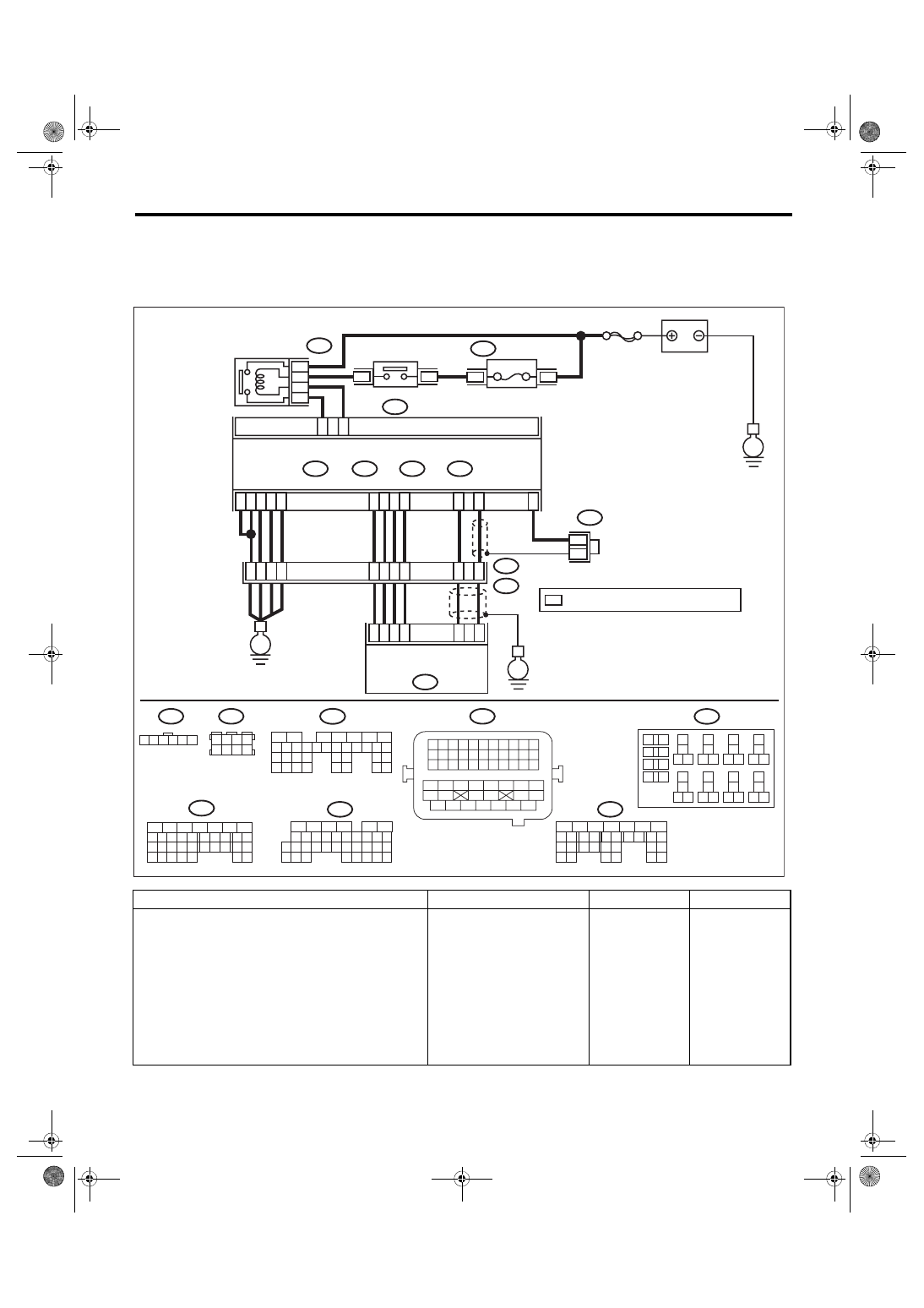
WIRING DIAGRAM:
• Engine electrical system, without SI-DRIVE <Ref. to WI-32, WITHOUT SI-DRIVE, WIRING DIAGRAM,
• Engine electrical system, with SI-DRIVE <Ref. to WI-48, WITH SI-DRIVE, WIRING DIAGRAM, Engine
Step
Check
Yes
No
1
CHECK HARNESS BETWEEN ECM AND
ELECTRONIC THROTTLE CONTROL CON-
NECTOR.
1) Turn the ignition switch to OFF.
2) Disconnect the connectors from ECM and
electronic throttle control.
3) Measure the resistance between ECM con-
nector and chassis ground.
Connector & terminal
(B134) No. 19 — Chassis ground:
(B134) No. 28 — Chassis ground:
Is the resistance 1 MΩ or
more?
Repair the ground
short circuit of har-
ness between
ECM connector
and electronic
throttle control
connector.
ECM
EN-08727
5
6
7
8
2
1
9
4
3
10
24
22 23
25
11 12 13 14 15
26 27
28
16 17
18 19 20 21
33 34
29
32
30 31
B136
C:
B134
A:
36
35
34
40
B17
B7
D3
A29
6
E2
B21
A1
8
C4
A2
8
6
4
25
*
*
B122
24
3
8
39
2
8
A2
A1
A19
A6
A3
D1
A4
3
E57
2
1
5
B134
B220
B220
31
29
32
A:
B137
B136
D:
C:
B135
B:
*
30
21
22
15A
B220
3
4
B135
B:
35
34
33
32
31
30
29
21
20
19
18
17
16
28
27
26
15
14
13
12
11
25
23
22
24
10
3
4
9
1
2
8
7
6
5
B220
18
19
6
7
4
3
5
2
1
12
11
10
9
8
40
36 39
38
37
34
33
35
32
28 31
30
29
23
22
21
20
26
25
24
27
17
16
15
14
13
B122
8
7
6
5
4
3
2
1
B21
33
32
31
30
29
28
27
26
47
46
45
44
43
42
54
53
52
51
50
49
48
41
40
39
38
37
36
35
34
25
24
23
22
21
20
19
18
17
16
15
14
13
12
11
10
9
8
7
6
5
4
3
2
1
D: B137
26
25
24
23
22
18
28
27
17
16
15
14
13
31
30
29
21
20
19
12
11
10
4
3
6
5
9
8
7
2
1
E57
6
5
4
3
2
1
35
34
33
32
7
26
25
24
23
22
18
28
27
17
16
15
14
13
31
30
29
21
20
19
12
11
10
4
3
6
5
9
8
2
1
E
E
E
SBF-7
FUSE
(RELAY BLOCK)
MAIN RELAY
ELECTRONIC THROTTLE
CONTROL RELAY
BATTERY
: TERMINAL No. OPTIONAL ARRANGEMENT
ELECTRONIC THROTTLE
CONTROL
EN(H4DOTC)(diag)-179
Diagnostic Procedure with Diagnostic Trouble Code (DTC)
ENGINE (DIAGNOSTICS)
2
CHECK SHORT CIRCUIT INSIDE THE ECM.
1) Connect the connector to ECM.
2) Measure the resistance between electronic
throttle control connector and engine ground.
Connector & terminal
(E57) No. 4 — Engine ground:
Is the resistance 1 MΩ or
more?
Step
Check
Yes
No
Нет комментариевНе стесняйтесь поделиться с нами вашим ценным мнением.
Текст