Subaru Impreza 3 / Impreza WRX / Impreza WRX STI. Service manual — part 741
EI-51
Console Box
EXTERIOR/INTERIOR TRIM
17.Console Box
A: REMOVAL
1) Disconnect the ground cable from the battery.
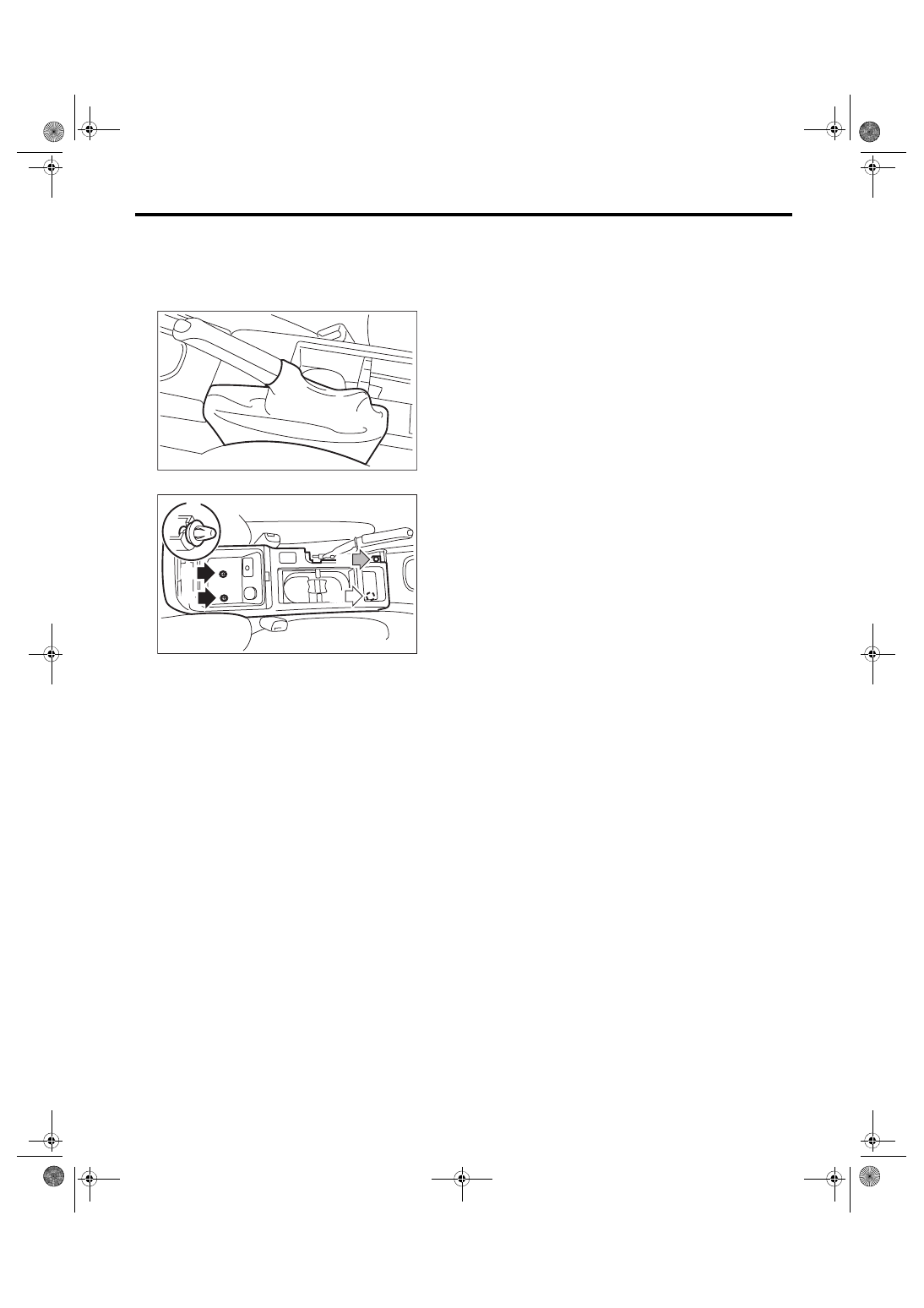
2) Remove the parking brake lever boot.
3) Remove the bolt (A), screw (B) and clip (C).
4) Disconnect the connector, and remove the con-
sole box.
B: INSTALLATION
Install each part in the reverse order of removal.
EI-00810
EI-02001
(B)
(A)
(A)
(C)
(C)
EI-52
Center Console
EXTERIOR/INTERIOR TRIM
18.Center Console
A: REMOVAL
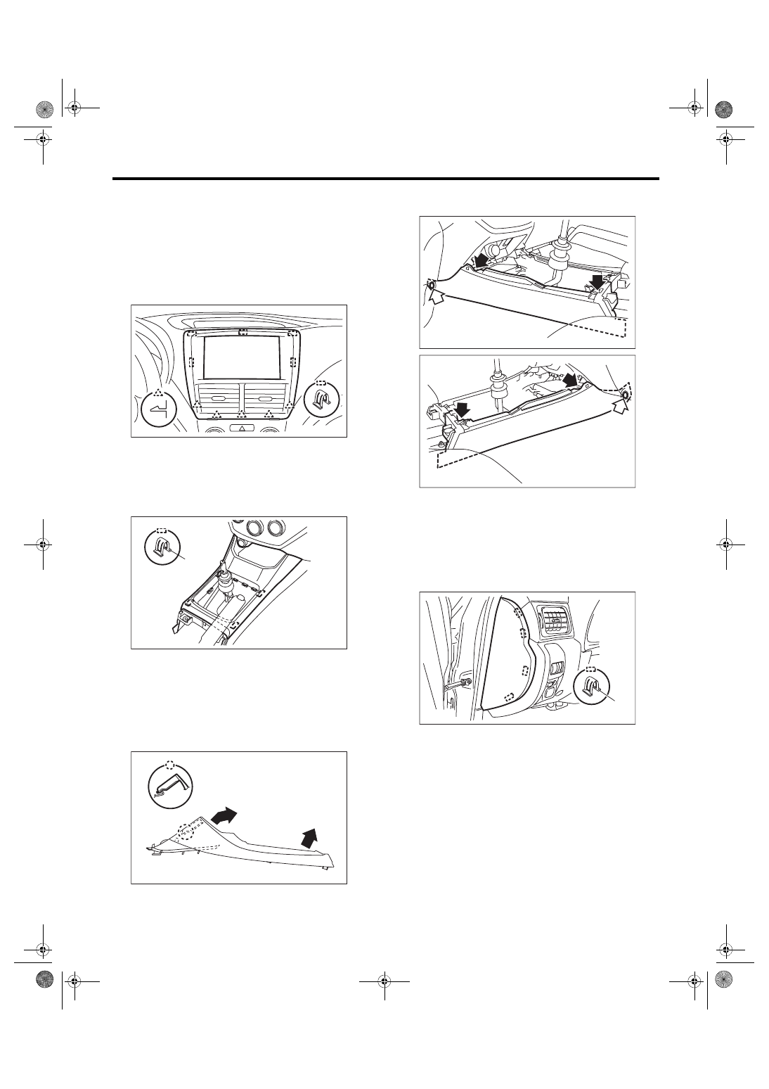
1. CENTER PANEL
1) Insert the lower slit of center panel to plastic clip
remover and then lift up the panel.
2) Remove the claws and plastic hook and then re-
move the center panel.
2. CONSOLE FRONT PANEL
1) Remove the console box. <Ref. to EI-51, RE-
2) Remove the shift knob.
3) Remove the console front panel.
(1) Remove the resin hook (A), and then lift up
the console front panel.
(2) Disconnect the connector and then remove
the console front panel.
NOTE:
When removing the console front panel, pull it in
the direction of the rear vehicle.
4) Remove the clips and screws, and remove the
console side cover.
NOTE:
Pull towards the rear of the vehicle to remove.
3. ORNAMENT PANEL
• Driver’s side
1) Remove the plastic hook (A), and remove the in-
strument panel side cover LH.
EI-02012
EI-02844
(A)
EI-02454
EI-02013
EI-02014
EI-01884
(A)
EI-53
Center Console
EXTERIOR/INTERIOR TRIM
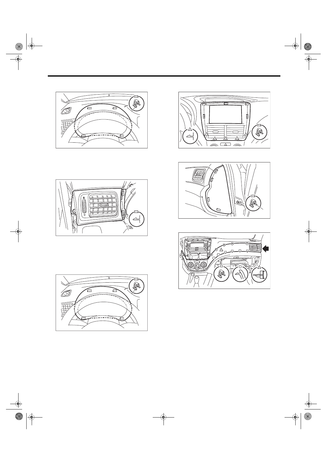
2) Remove the plastic hook (A), and detach the
meter visor.
NOTE:
Remove the plastic hook on the bottom side of the
meter visor by pulling it.
3) Detach the screw and the claw to take out orna-
ment panel LH.
• Passenger’s side
1) Remove the instrument panel lower cover. <Ref.
to EI-49, REMOVAL, Instrument Panel Lower Cov-
2) Remove the plastic hook (A), and detach the
meter visor.
NOTE:
Remove the plastic hook on the bottom side of the
meter visor by pulling it.
3) Insert a plastic clip remover into the slit at the
bottom of the center panel, to lift the panel.
4) Remove the claws and resin hook and then re-
move the center panel.
5) Detach the plastic hook (A), and remove the in-
strument panel side cover RH.
6) Detach the screws and the plastic hooks to re-
move ornament panel RH.
7) Disconnect connectors.
EI-01893
(A)
EI-01894
EI-01893
(A)
EI-02012
EI-01895
(A)
EI-02845
EI-54
Center Console
EXTERIOR/INTERIOR TRIM
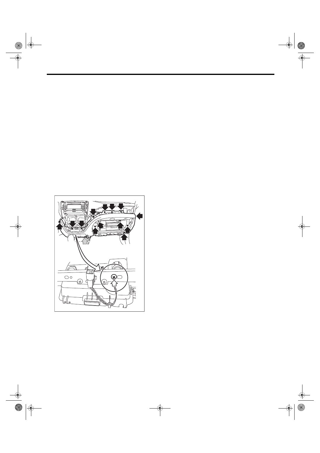
4. INSTRUMENT PANEL LOWER
1) Remove the console box. <Ref. to EI-51, RE-
2) Remove the center panel. <Ref. to EI-52, CEN-
TER PANEL, REMOVAL, Center Console.>
3) Remove the console front panel. <Ref. to EI-52,
CONSOLE FRONT PANEL, REMOVAL, Center
4) Remove ornament panel RH. <Ref. to EI-52,
ORNAMENT PANEL, REMOVAL, Center Con-
5) Remove the instrument panel lower cover. <Ref.
to EI-49, REMOVAL, Instrument Panel Lower Cov-
6) Remove the glove box lid. <Ref. to EI-49, RE-
MOVAL, Instrument Panel Lower Cover.>
7) Remove the screws and nuts, and remove the
instrument panel lower.
NOTE:
The screws indicated with the white arrows are
tightened from the opposing side.
B: INSTALLATION
Install each part in the reverse order of removal.
Tightening torque:
7.5 N·m (7.6 kgf-m, 5.5 ft-lb)
EI-01829
Нет комментариевНе стесняйтесь поделиться с нами вашим ценным мнением.
Текст