Subaru Impreza 3 / Impreza WRX / Impreza WRX STI. Service manual — part 742
EI-55
Instrument Panel Assembly
EXTERIOR/INTERIOR TRIM
19.Instrument Panel Assembly
A: REMOVAL
CAUTION:
Be careful not to damage the airbag system
harness when servicing the instrument panel.
Damage may cause the system to malfunction.
1) Disconnect the ground cable from battery.
2) Remove the front pillar upper trim. <Ref. to EI-
59, REMOVAL, Upper Inner Trim.>
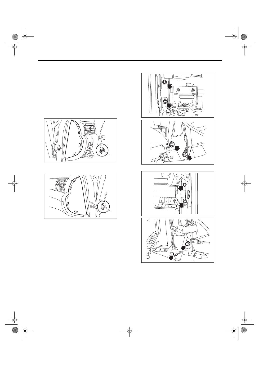
3) Remove the plastic hook (A), and remove the in-
strument panel side cover LH.
4) Detach the plastic hook (A), and remove the in-
strument panel side cover RH.
5) Remove the console box. <Ref. to EI-51, RE-
6) Remove the console front panel. <Ref. to EI-52,
CONSOLE FRONT PANEL, REMOVAL, Center
7) Remove the instrument panel lower cover. <Ref.
to EI-49, REMOVAL, Instrument Panel Lower Cov-
8) Remove the steering shaft assembly. <Ref. to
PS-16, REMOVAL, Steering Column.>
9) Disconnect connectors.
NOTE:
To make reassembly easier, place matching mark-
ings on connectors as necessary.
10) Remove the bolts and fuse box on the driver’s
side.
11) Remove the bolts on the passenger’s side.
12) Make sure that the connectors are disconnect-
ed, and remove the instrument panel from the vehi-
cle.
CAUTION:
When taking the instrument panel out of the ve-
hicle, be careful not to damage the vehicle. Per-
form this work by a group of two persons or
more.
EI-01884
(A)
EI-01895
(A)
EI-01896
EI-01853
EI-01897
EI-01854
EI-56
Instrument Panel Assembly
EXTERIOR/INTERIOR TRIM
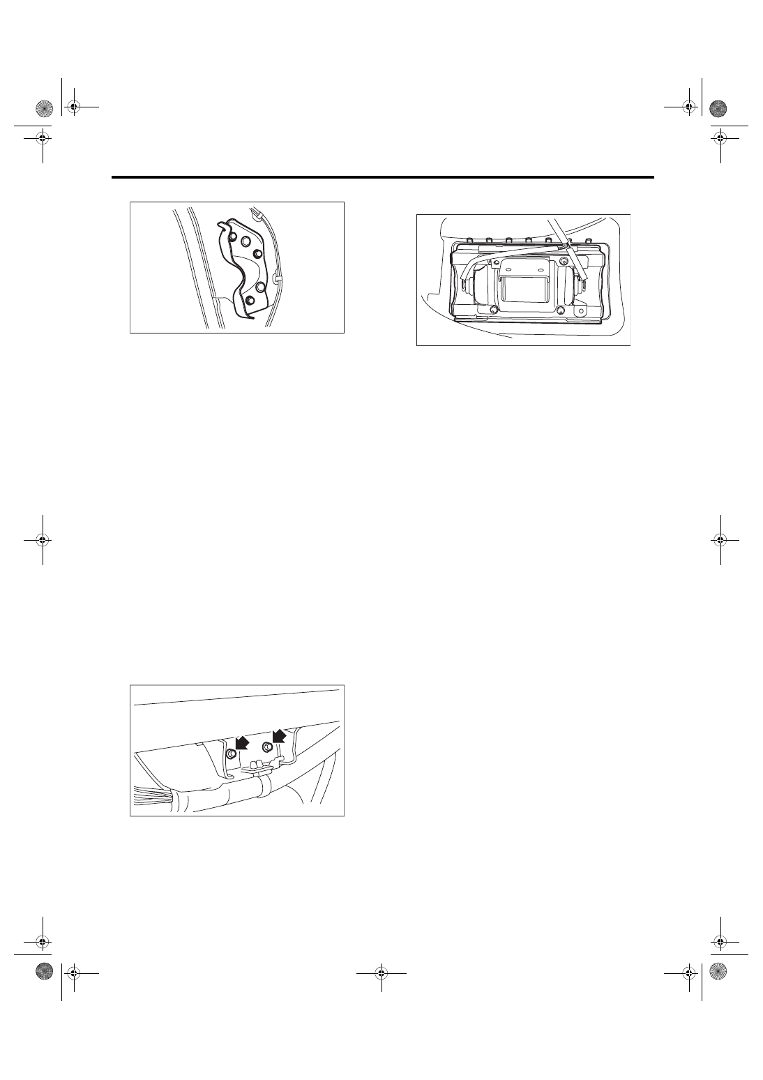
13) Remove the steering support beam bracket.
B: INSTALLATION
1) Insert the matching pins (three locations) on the
body side into the instrument panel assembly.
2) Check that the matching pins are inserted se-
curely, and then route the harness.
3) Install each part in the reverse order of removal.
Tightening torque:
Steering support beam & steering support
beam bracket: 25 N·m (2.55 kgf-m, 18.4 ft-lb)
Steering shaft: <Ref. to PS-4, STEERING
WHEEL AND COLUMN, COMPONENT, Gen-
Instrument panel lower: 7.5 N·m (0.76 kgf-m,
5.5 ft-lb)
C: DISASSEMBLY
1) Remove the combination meter assembly. <Ref.
to IDI-16, REMOVAL, Combination Meter.>
2) Remove the audio. <Ref. to ET-6, REMOVAL,
3) Remove the GPS antenna. <Ref. to ET-15, RE-
4) Remove the heater vent duct. <Ref. to AC-51,
5) Remove the bolts securing the passenger’s side
airbag module to the steering support beam.
6) Remove the claws, and remove the passenger’s
airbag module.
D: ASSEMBLY
CAUTION:
Be careful with the wiring harness routing dur-
ing installation. When installing to the vehicle
body, pinching the wiring harness may cause
open circuits and shorts.
Attach each part in the reverse order of disassem-
bly, until the instrument panel assembly is formed.
NOTE:
Method of installing insulator
• Adhesive
Use polyurethane adhesive. When assembling the
instrument panel assembly, wait until the adhesive
has evaporated to prevent filling of the smell in the
compartment.
• Double-sided tape
Use commercial double-sided tape. (Use strong
double-sided adhesive tape.)
Tightening torque:
Instrument panel lower: 7.5 N·m (0.76 kgf-m,
5.5 ft-lb)
Passenger’s airbag module: 7.5 N·m (0.76
kgf-m, 5.5 ft-lb)
EI-01855
EI-00610
AB-01901
EI-57
Lower Inner Trim
EXTERIOR/INTERIOR TRIM
20.Lower Inner Trim
A: REMOVAL
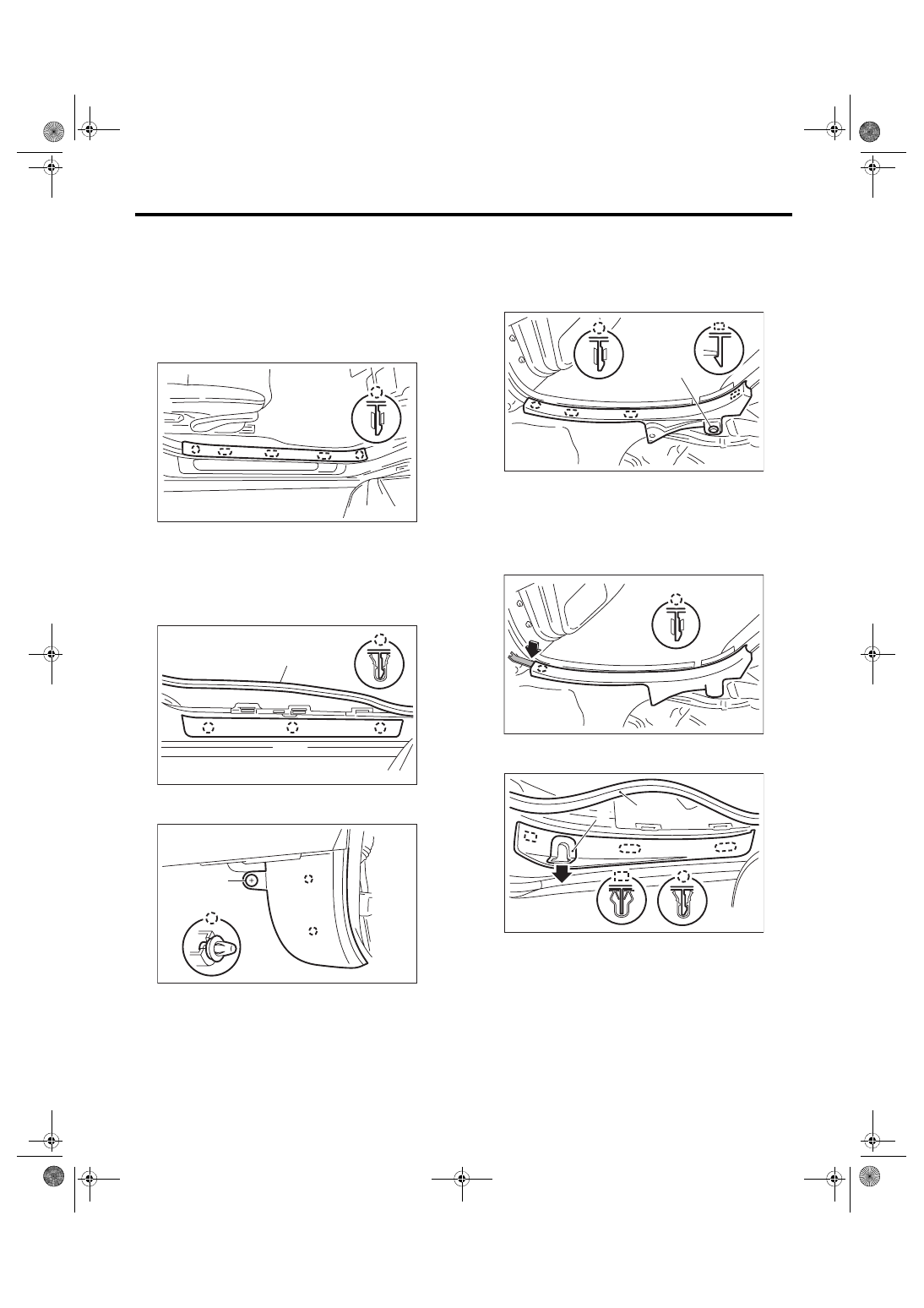
1) Remove the hook, and remove the inside scuff
plate.
CAUTION:
Do not pull with excessive force. Doing so may
damage the scuff plate.
NOTE:
It is easier to remove the weather strip and pull off
the floor mat to detach the claw of scuff plate from
the backside.
2) Remove the weather strip (A), and remove the
outside scuff plate.
3) Remove clip (A), and remove the front pillar low-
er trim.
4) Remove the rear seat cushion. <Ref. to SE-13,
5) Remove clip (A), and remove the inside scuff
plate.
CAUTION:
Do not pull with excessive force. Doing so may
damage the scuff plate.
NOTE:
• It is easier to remove the weather strip to detach
the claw of scuff plate from the backside of floor
mat.
• It is easier to detach the tip claw of scuff plate us-
ing a clip remover.
6) Remove weather strip (A) and door catcher cov-
er (B), then remove the outside scuff plate.
EI-01806
EI-01807
(A)
EI-01898
(A)
EI-01809
(A)
EI-02330
EI-01810
(A)
(B)
EI-58
Lower Inner Trim
EXTERIOR/INTERIOR TRIM
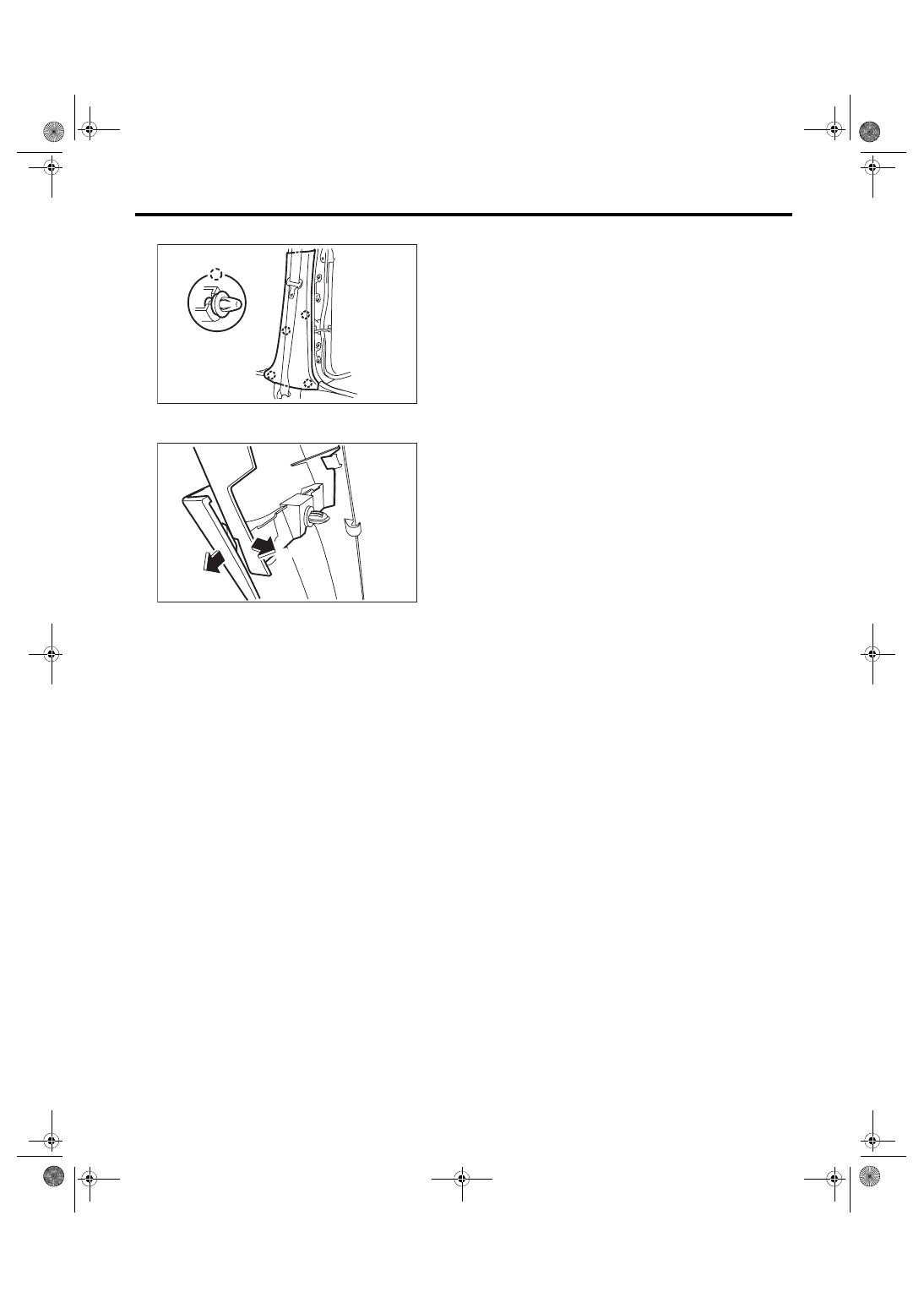
7) Remove the clips of the center pillar lower trim.
8) Spread the lower trim outwards to remove the
claw, and pull on the upper trim to remove.
B: INSTALLATION
Install each part in the reverse order of removal.
EI-01811
EI-01856
(1)
(2)
Нет комментариевНе стесняйтесь поделиться с нами вашим ценным мнением.
Текст