Subaru Impreza 3 / Impreza WRX / Impreza WRX STI. Service manual — part 21
PM-22
Transmission Gear Oil
PERIODIC MAINTENANCE SERVICES
14.Transmission Gear Oil
A: INSPECTION
1. 6MT MODEL
Refer to “6MT” section for transmission gear oil in-
spection. <Ref. to 6MT-26, INSPECTION, Trans-
2. 5MT MODEL
Refer to “5MT” section for transmission gear oil in-
spection. <Ref. to 5MT-22, INSPECTION, Trans-
B: REPLACEMENT
1. 6MT MODEL
Refer to “6MT” section for transmission gear oil re-
placement. <Ref. to 6MT-26, REPLACEMENT,
2. 5MT MODEL
Refer to “5MT” section for transmission gear oil re-
placement. <Ref. to 5MT-22, REPLACEMENT,
gi14usena07.fm 22 ページ 2013年9月10日 火曜日 午後3時59分
PM-23
Front & Rear Differential Gear Oil
PERIODIC MAINTENANCE SERVICES
15.Front & Rear Differential Gear
Oil
A: INSPECTION
1. FRONT DIFFERENTIAL
Refer to “6MT” or “5MT” section for front differential
gear oil inspection. <Ref. to 6MT-26, INSPEC-
TION, Transmission Gear Oil.> <Ref. to 5MT-22,
INSPECTION, Transmission Gear Oil.>
2. REAR DIFFERENTIAL
Refer to “DI” section for rear differential gear oil in-
spection. <Ref. to DI-18, INSPECTION, Differential
B: REPLACEMENT
1. FRONT DIFFERENTIAL
As well as transmission oil, differential oil is used to
lubricate the differential. Refer to “Transmission
Oil”. <Ref. to PM-22, Transmission Gear Oil.>
2. REAR DIFFERENTIAL
Refer to “DI” section for rear differential gear oil re-
placement. <Ref. to DI-19, REPLACEMENT, Dif-
gi14usena07.fm 23 ページ 2013年9月10日 火曜日 午後3時59分
PM-24
Brake Line
PERIODIC MAINTENANCE SERVICES
16.Brake Line
A: INSPECTION
1. BRAKE LINE
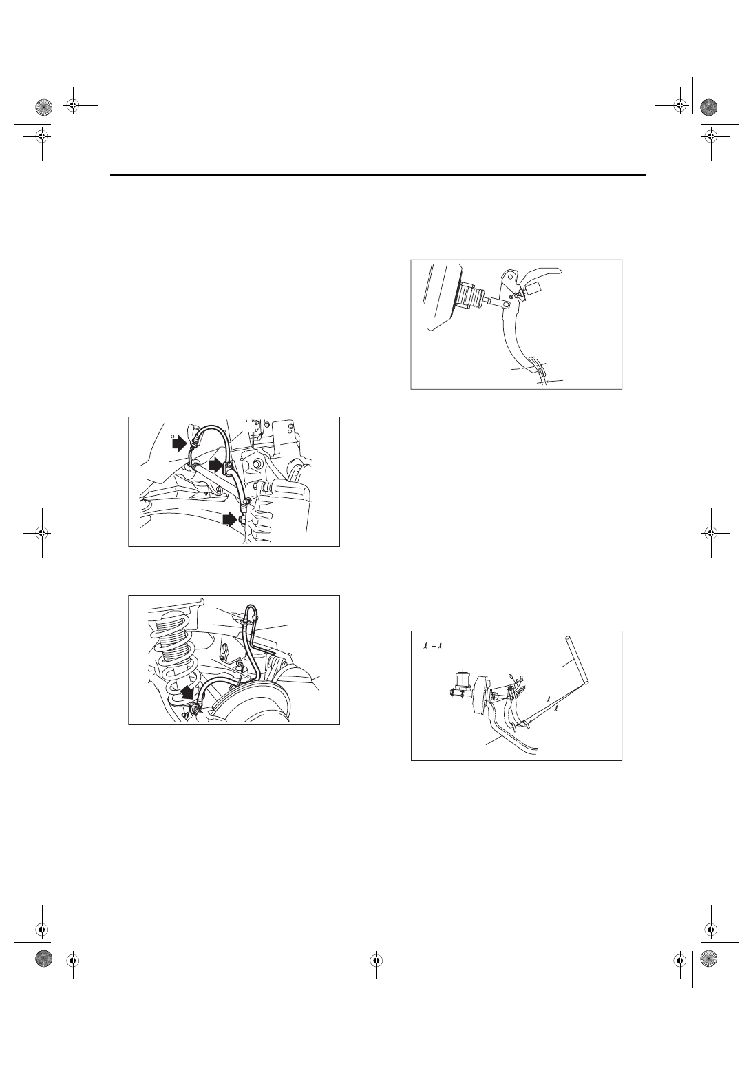
1) Check for scratches, swelling, corrosion, traces
of fluid leakage on the brake hoses or pipe joints.
2) Check the possibility of adjacent parts interfering
with brake pipes/hoses during driving, and loose
connections/clamps.
3) Check any trace of fluid leakage, scratches, etc.
on master cylinder and wheel cylinder.
NOTE:
• When the brake fluid level in the reservoir tank is
lower than specified limit, the brake warning light
on the combination meter will illuminate.
• Visually check the brake hose for damage. (Use
a mirror where it is difficult to see)
2. SERVICE BRAKE
1) Move to the pull-up direction with the force of
less than 10 N (1 kgf, 2 lbf) and check the free play.
Brake pedal play
0.5 — 2.0 mm (0.02 — 0.08 in)
2) If the free play is out of specifications above, ad-
just the brake pedal. <Ref. to BR-48, INSPEC-
3) Check the pedal stroke.
While the engine is idling, depress the brake pedal
with a 490 N (50 kgf, 110 lbf) load and measure the
distance between the brake pedal and steering
wheel. With the brake pedal released, measure the
distance between pedal and steering wheel again.
The difference between the two measured values
must be the specified value or less. If the measured
value is greater than or equal to the specification,
there is possibility of entering air in hydraulic unit.
Brake pedal stroke A:
110 mm (4.33 in)/ 490 N (50 kgf, 110 lbf) or
less
4) Check to see if air is in the brake fluid pressure
line by the feel of pedal operation. If air appears to
exist in the fluid pressure line, bleed it from the sys-
tem.
5) Check for even operation of all brakes, using a
brake tester or by driving the vehicle for a short dis-
tance on a straight road.
(1) Front brake hose
(2) Front brake pipe
(1) Rear brake pipe
(2) Rear brake hose
(3) Clamp
PM-00385
(1)
(2)
PM-00386
(3)
(2)
(3)
(1)
(A) Pedal free play
(A) Steering wheel
(B) Toe board
PM-00412
(A)
(B)
(A)
= A
1
1
2
2
PM-00045
gi14usena07.fm 24 ページ 2013年9月10日 火曜日 午後3時59分
PM-25
Brake Line
PERIODIC MAINTENANCE SERVICES
3. BRAKE SERVO SYSTEM
1) With the engine off, depress the brake pedal
several times applying the same pedal force. Make
sure the travel distance should not change.
2) With the brake pedal depressed, start the en-
gine. Make sure the pedal should move slightly to-
ward the floor.
3) With the brake pedal depressed, stop the engine
and keep the pedal depressed for 30 seconds.
Make sure the pedal height should not change.
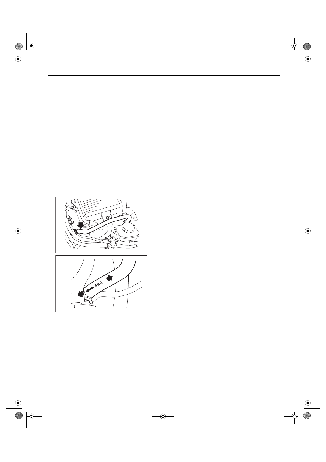
4) A check valve is built into the vacuum hose. Dis-
connect the vacuum hose to inspect function of
check valve.
Blow compressed air into vacuum hose from the
end of brake booster side. Check that the air flows
from the air hose on engine side. Next blow air into
hose from engine side: Check that the air does not
flow from the hose.
Replace the both check valve and vacuum hose if
the check valve is faulty. Engine side of vacuum
hose is indicated by marking “ENG” as shown.
5) Check the vacuum hose for cracks or other dam-
age.
NOTE:
When installing the vacuum hose on the engine
and brake booster, do not use soapy water or lubri-
cating oil on their connections.
6) Check the vacuum hose to make sure it is tightly
secured.
(A) Engine side
(B) Brake booster side
PM-00427
(B)
(A)
PM-00434
gi14usena07.fm 25 ページ 2013年9月10日 火曜日 午後3時59分
Нет комментариевНе стесняйтесь поделиться с нами вашим ценным мнением.
Текст