Subaru Impreza 3 / Impreza WRX / Impreza WRX STI. Service manual — part 424
6MT-33
Manual Transmission Assembly
MANUAL TRANSMISSION AND DIFFERENTIAL
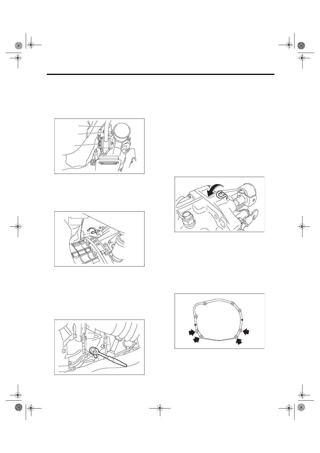
25) Move the transmission to the right side of the
vehicle, and remove the joint COMPL, stay bolts
and reverse check cable.
NOTE:
If the transmission is not moved aside, the joint
COMPL and stay bolts may contact the body and
cause damage.
26) Tighten the turnbuckle of the ST to tilt the en-
gine assembly towards the back.
27) Remove the bolts and nuts holding the bottom
of transmission to the engine, and remove the
transmission from the vehicle.
NOTE:
• During removal, be careful not to hit the trans-
mission against the body when pulling towards the
rear.
• The clutch pipe and breather pipe may interfere
with each other. Remove carefully.
B: INSTALLATION
1) Set the release fork, release bearing and release
shaft to the transmission. <Ref. to CL-15, INSTAL-
LATION, Release Bearing and Lever.>
2) Replace the front differential side retainer oil
seal. <Ref. to 6MT-28, REPLACEMENT, Differen-
tial Side Retainer Oil Seal.>
NOTE:
Be sure to replace the differential side oil seal after
the procedure of removing front drive shaft from
transmission.
3) Strike and bend the transmission hanger of
transmission rear with a rubber hammer etc. so that
it gets in contact with the transmission case.
CAUTION:
Do not apply extra overload or impact to the
transmission case.
4) Install the transmission onto the engine.
5) Tighten the bolts and nuts which hold the lower
side of transmission to the engine.
NOTE:
• Make sure that the main shaft spline is complete-
ly inserted.
• Make sure that the rear end of the engine is set
low.
Tightening torque:
50 N·m (5.1 kgf-m, 36.9 ft-lb)
(A) Joint COMPL bolt
(B) Stay bolt
(C) Reverse check cable
MT-00886
(C)
(A)
(B)
MT-00463
MT-01090
MT-02303
MT-00464
6MT-34
Manual Transmission Assembly
MANUAL TRANSMISSION AND DIFFERENTIAL
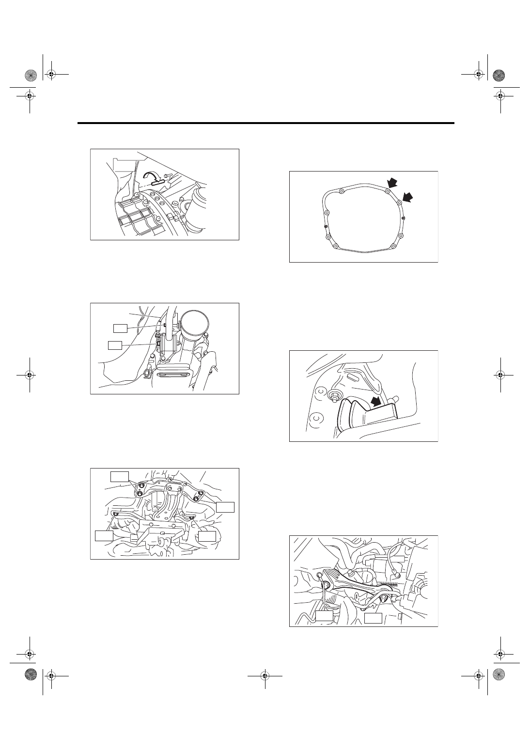
6) Loosen the turnbuckle of ST to return the engine
to its original position.
7) Move the transmission to the right side of the ve-
hicle, and attach the joint COMPL, stay bolts and
reverse check cable.
Tightening torque:
T1: 12 N·m (1.2 kgf-m, 8.9 ft-lb)
T2: 32 N·m (3.3 kgf-m, 23.6 ft-lb)
8) Install the front crossmember and rear cross-
member.
Tightening torque:
T1: 70 N·m (7.1 kgf-m, 51.6 ft-lb)
T2: 140 N·m (14.3 kgf-m, 103 ft-lb)
9) Lower the vehicle.
10) Tighten the bolts which hold the upper side of
the transmission to the engine.
Tightening torque:
50 N·m (5.1 kgf-m, 36.9 ft-lb)
11) Make sure that the release bearing is com-
pletely inserted.
NOTE:
• Push the release fork towards the operating cyl-
inder side until a clicking sound is heard. Pull the
release fork towards the engine side. If the release
fork is not in contact with the case, the setting is
complete.
• Confirm that the boot cover is set securely.
12) Install the pitching stopper bracket, return
spring bracket, and transmission radio ground ca-
ble.
Tightening torque:
41 N·m (4.2 kgf-m, 30.2 ft-lb)
13) Install the pitching stopper.
Tightening torque:
T1: 50 N·m (5.1 kgf-m, 36.9 ft-lb)
T2: 58 N·m (5.9 kgf-m, 42.8 ft-lb)
(A) Reverse check cable
MT-01527
MT-00465
(A)
T2
T1
MT-01265
T1
T2
T2
T1
MT-01524
MT-00467
MT-01301
T1
T2
6MT-35
Manual Transmission Assembly
MANUAL TRANSMISSION AND DIFFERENTIAL
14) Install the return spring.
15) Install the clutch operating cylinder.
Tightening torque:
41 N·m (4.2 kgf-m, 30.2 ft-lb)
NOTE:
Check that the clutch hose is routed properly.
16) Install the starter assembly. <Ref. to SC(STI)-
17) Install the transmission radio ground terminal.
18) Install the secondary air combination valve.
<Ref. to EC(STI)-30, SECONDARY AIR COMBI-
NATION VALVE LH, INSTALLATION, Secondary
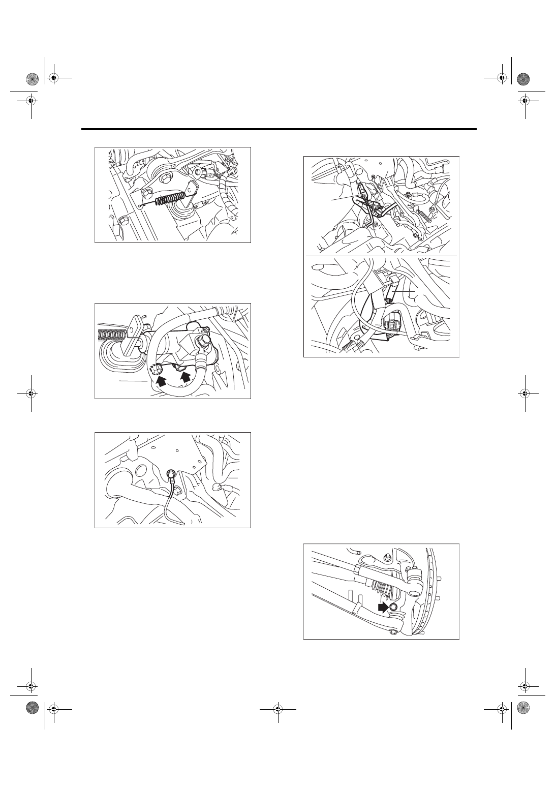
19) Connect the following harness connectors,
then attach the engine hanger rear.
20) Lift up the vehicle.
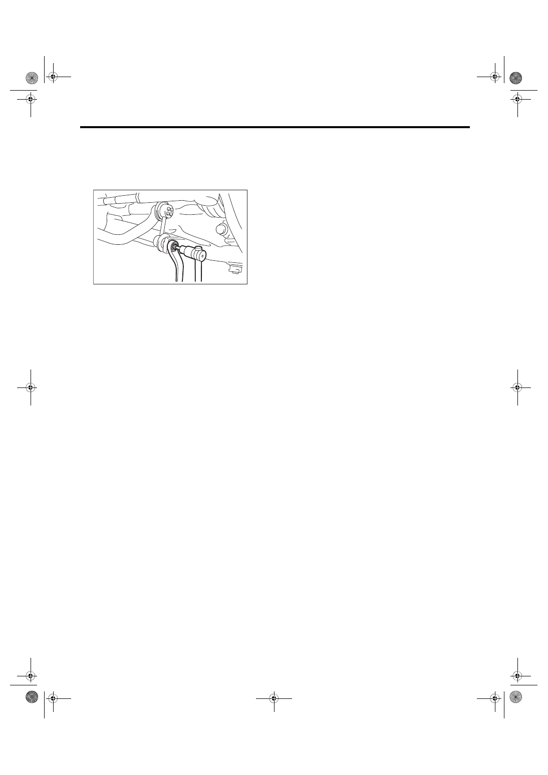
21) Set the ST to side retainer.
ST 28399SA010 OIL SEAL PROTECTOR
22) Install the front drive shaft into the transmis-
sion.
NOTE:
Replace the circlip of drive shaft with a new part.
23) Install the front drive shaft into transmission, re-
move the ST and insert the drive shaft securely.
ST 28399SA010 OIL SEAL PROTECTOR
24) Install the ball joint of the front arm.
Tightening torque:
50 N·m (5.1 kgf-m, 36.9 ft-lb)
MT-02302
CL-00445
MT-01266
(A) Front oxygen (A/F) sensor connector
(B) Rear oxygen sensor connector
(C) Neutral position switch backup light switch con-
nector
MT-01740
(A)
(B)
(C)
FS-00106
6MT-36
Manual Transmission Assembly
MANUAL TRANSMISSION AND DIFFERENTIAL
25) Install the front stabilizer link.
Tightening torque:
45 N·m (4.6 kgf-m, 33.2 ft-lb)
NOTE:
Use a new self-locking nut.
26) Install the propeller shaft. <Ref. to DS-12, IN-
27) Install the heat shield cover.
28) Install the center exhaust pipe. <Ref. to
EX(STI)-9, INSTALLATION, Center Exhaust
29) Fill the transmission gear oil. <Ref. to 6MT-26,
REPLACEMENT, Transmission Gear Oil.>
30) Install the transmission under cover.
31) Install the intercooler. <Ref. to IN(STI)-13, IN-
32) Connect the battery ground terminal.
FS-00117
Нет комментариевНе стесняйтесь поделиться с нами вашим ценным мнением.
Текст