Subaru Impreza 3 / Impreza WRX / Impreza WRX STI. Service manual — part 694
GW-9
Power Window Control Switch
GLASS/WINDOWS/MIRRORS
3. Power Window Control
Switch
A: REMOVAL
1. MAIN SWITCH
1) Disconnect the ground cable from battery.
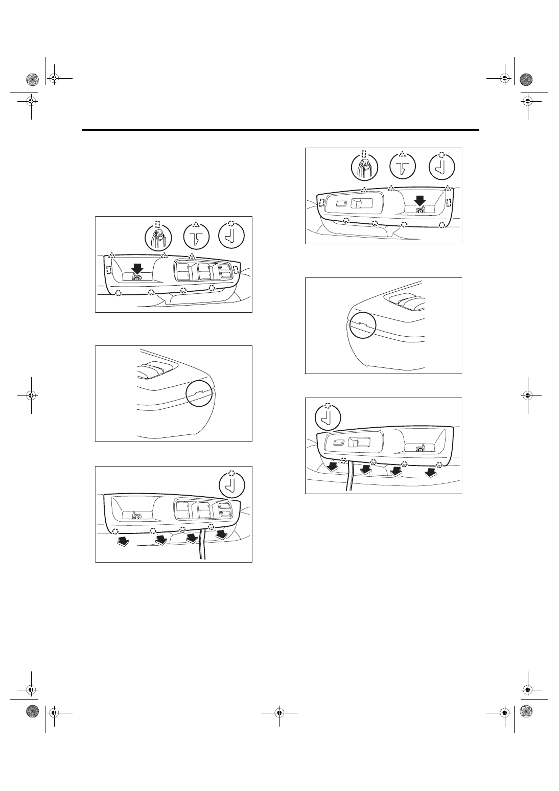
2) Remove the power window switch panel.
(1) Open the cover and remove the screws.
(2) Lift up the tip of switch panel by using a plas-
tic remover.
(3) Disengage the end face tabs by using a
plastic remover.
(4) Remove the power window switch panel.
3) Disconnect the main switch connector.
4) Remove the screws to remove the power win-
dow main switch assembly.
2. SUB-SWITCH
1) Disconnect the ground cable from battery.
2) Remove the power window switch panel.
(1) Open the cover and remove the screws.
(2) Lift up the tip of switch panel by using a plas-
tic remover.
(3) Disengage the end face tabs by using a
plastic remover.
(4) Remove the power window switch panel.
3) Disconnect the power window sub-switch con-
nector.
4) Remove the screws to remove the power win-
dow sub-switch assembly.
B: INSTALLATION
CAUTION:
After installation of main switch, always per-
form the reset operation A (initial setting).
Failure to do so may cause the improper activa-
tion of auto-reverse operation for pinching haz-
ard prevention. <Ref. to GW-8, RESET
OPERATION A, INSPECTION, Power Window
Install each part in the reverse order of removal.
EI-03082
GW-00668
GW-00936
GW-00972
GW-00637
GW-00938
GW-10
Power Window Control Switch
GLASS/WINDOWS/MIRRORS
C: INSPECTION
1. MAIN SWITCH
• Driver’s seat
CAUTION:
Since the driver’s side power window switch is
controlled by CPU, do not check continuity for
switch alone with the circuit tester. Performing
continuity check with circuit tester may dam-
age the driver’s side power window switch cir-
cuit.
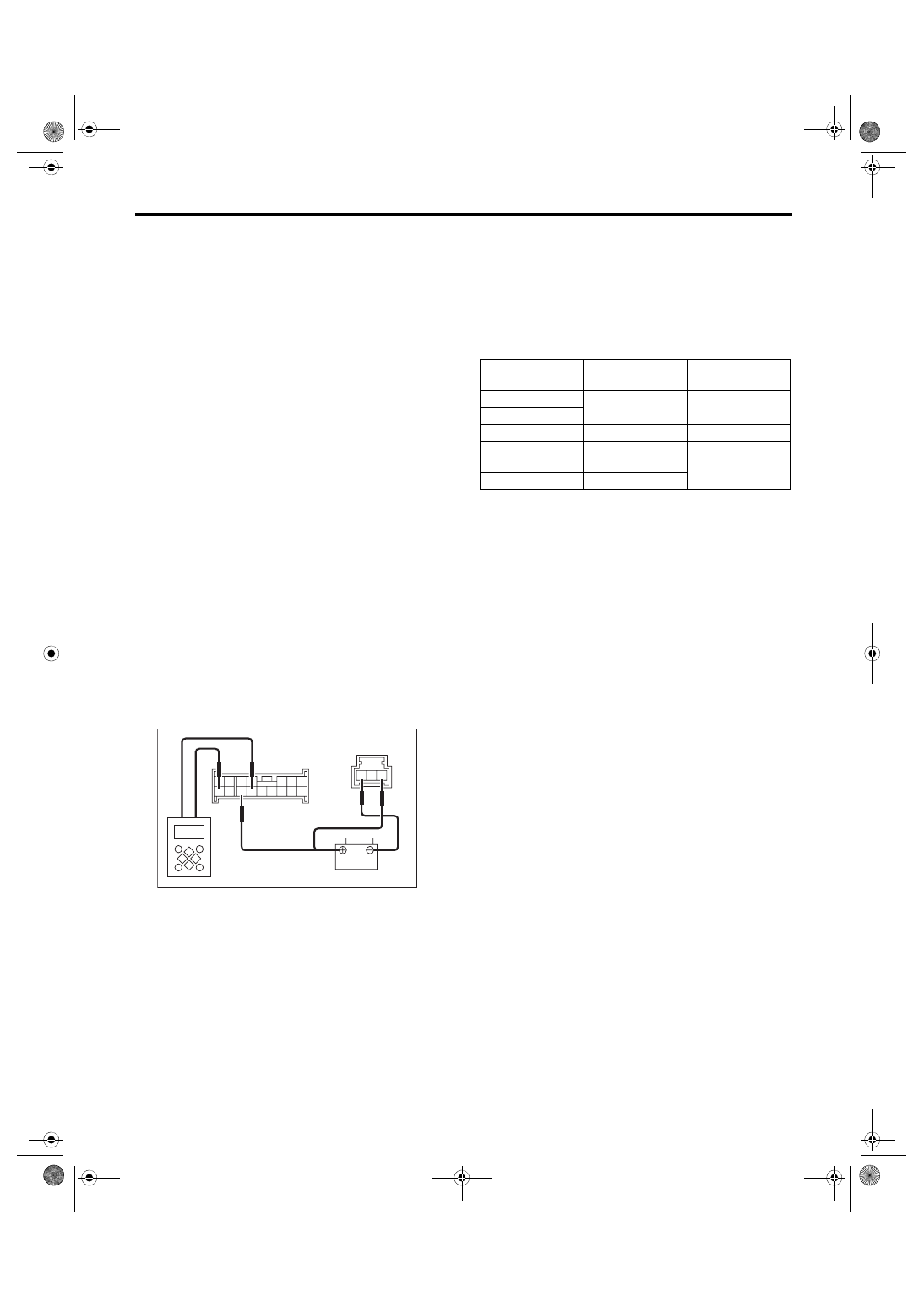
Check output from the power window main switch
to driver’s side motor using the oscilloscope func-
tion in the Subaru Select Monitor.
1) Disconnect the ground cable from battery.
2) Remove the power window main switch. <Ref. to
GW-9, REMOVAL, Power Window Control
3) Connect the battery and the Subaru Select Mon-
itor to the power window main switch connector.
CAUTION:
Never mix up the terminals when connecting
the power window main switch connector and
battery. If connected to a wrong terminal, the
power window main switch may be damaged.
NOTE:
• When the battery is connected to the power win-
dow main switch, the letters “AUTO” on the driver’s
side knob illuminates.
• For detailed procedures, refer to “Subaru Select
Monitor Operation Manual”.
4) Operate the driver’s side power window switch
knob and check the output.
NOTE:
Since output time during window UP operation is
extremely short, it cannot be checked without using
a measuring instrument such as oscilloscope. Out-
put is constantly produced while the knob is operat-
ed for window DOWN operation.
5) Replace the power window main switch if the in-
spection result is not within the standard value.
(1) Power window main switch connector (16
poles)
(2) Power window main switch connector (3 poles)
(3) Subaru Select Monitor
GW-00966
1
2
3
8
10
4
11
12
13
14
15
16
5
6
7
17
18
19
(3)
9
(1)
(2)
Switch knob posi-
tion
Output time
Standard
AUTO UP
150 ms
Battery voltage
UP
OFF
—
0 V
DOWN
During switch
knob operation
Battery voltage
AUTO DOWN
Approx. 300 ms
GW-11
Power Window Control Switch
GLASS/WINDOWS/MIRRORS
• Except for driver’s seat
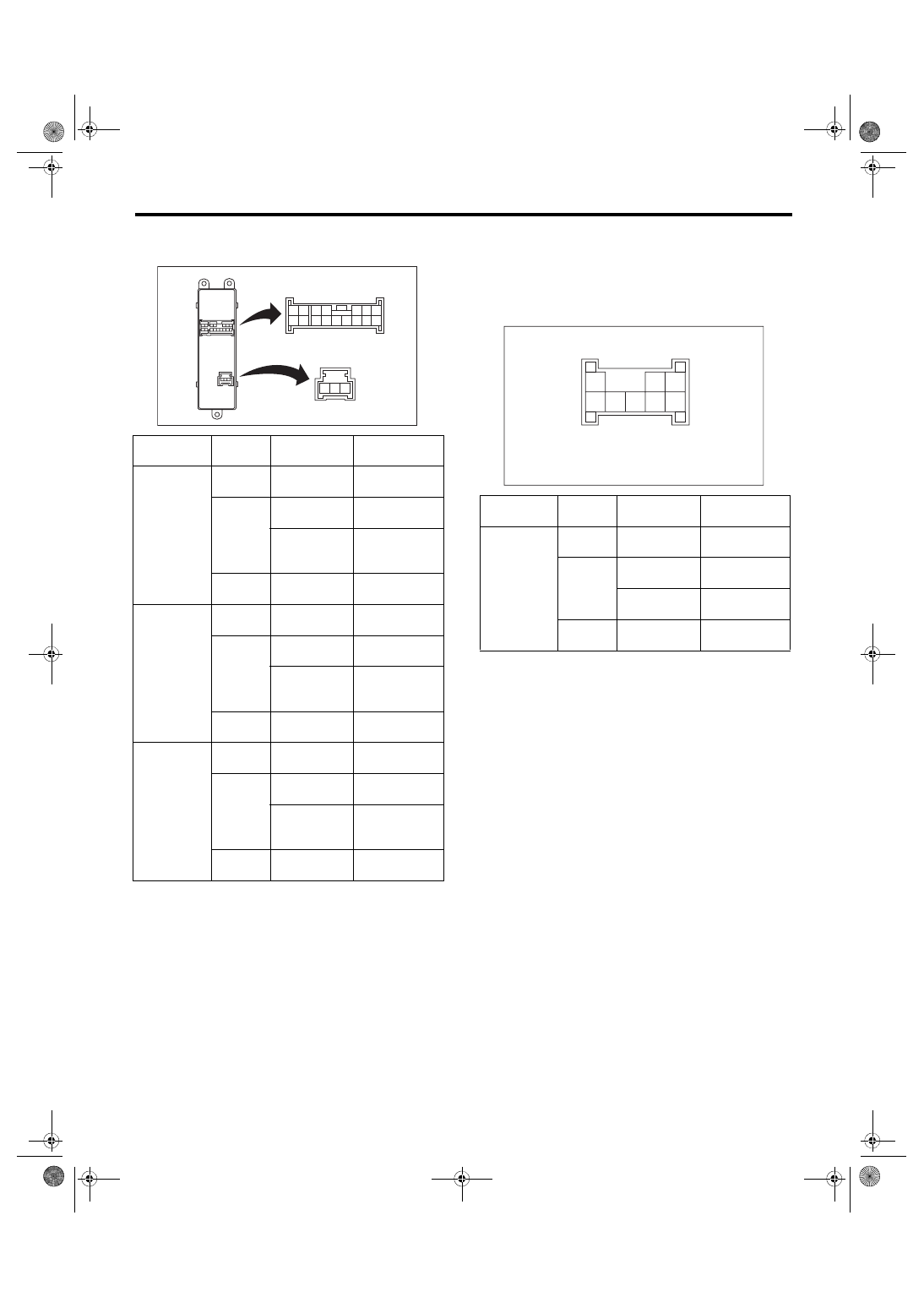
1) Check the resistance between switch terminals.
2) Replace the power window main switch if the in-
spection result is not within the standard value.
2. SUB-SWITCH
1) Remove the sub-switch. <Ref. to GW-9, SUB-
SWITCH, REMOVAL, Power Window Control
2) Check the resistance between sub-switch termi-
nals.
3) Replace the power window sub-switch if the in-
spection result is not within the standard value.
Switch
position
Terminal No.
Standard
Passenger’s
seat
UP
14 and 8
12 and 19
Less than 1 Ω
OFF
14 and 12
14 and 8
1 MΩ or more
8 and 12
8 and 19
12 and 19
Less than 1 Ω
DOWN
14 and 12
8 and 19
Less than 1 Ω
Rear LH
UP
14 and 7
5 and 19
Less than 1 Ω
OFF
14 and 7
14 and 5
1 MΩ or more
19 and 7
19 and 5
7 and 5
Less than 1 Ω
DOWN
14 and 5
7 and 19
Less than 1 Ω
Rear RH
UP
14 and 1
3 and 19
Less than 1 Ω
OFF
14 and 1
14 and 3
1 MΩ or more
19 and 3
19 and 1
3 and 1
Less than 1 Ω
DOWN
14 and 3
1 and 19
Less than 1 Ω
1
2
3
8
9
10
4
11
12
13
14
15
16
5
6
7
17
18
19
GW-00638
Switch
position
Terminal No.
Standard
Passenger
seat, rear
UP
4 and 5
6 and 7
Less than 1 Ω
OFF
7 and 4
8 and 4
1 MΩ or more
5 and 8
6 and 7
Less than 1 Ω
DOWN
4 and 6
5 and 8
Less than 1 Ω
GW-00478
1
2
3
4
5
6
7
8
GW-12
Front Door Glass
GLASS/WINDOWS/MIRRORS
4. Front Door Glass
A: REMOVAL
1) Remove the front door trim. <Ref. to EI-45,
FRONT DOOR, REMOVAL, Door Trim.>
2) Remove the sealing cover. <Ref. to EB-21, RE-
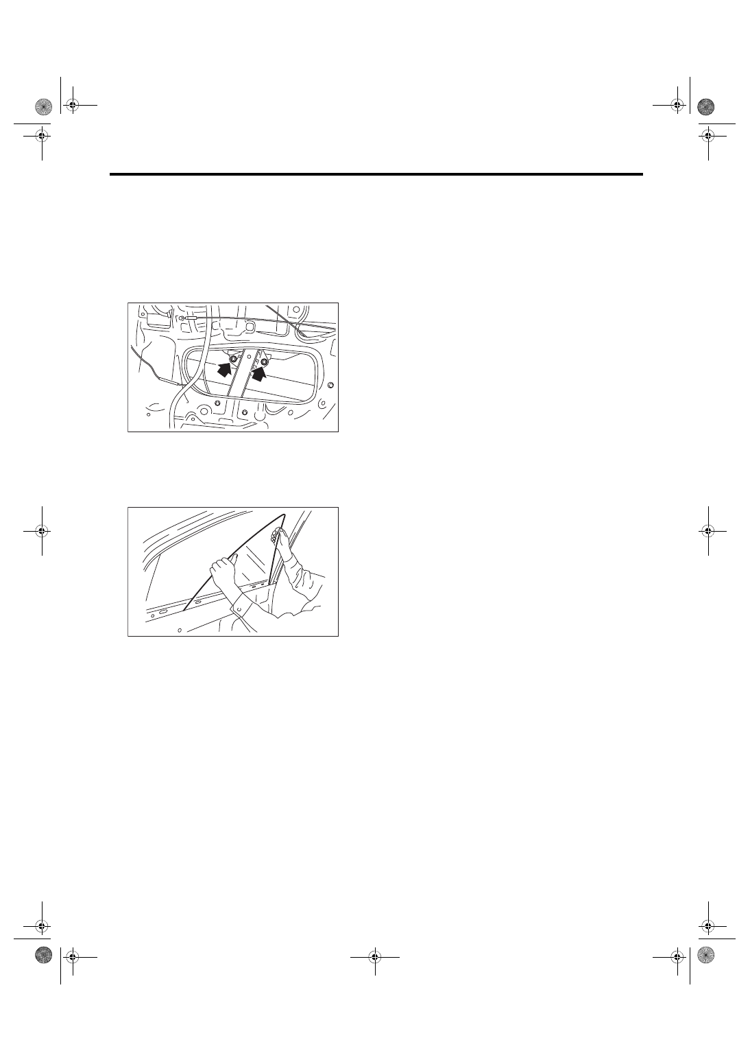
3) Operate the power window switch to move the
glass, and remove the bolts.
4) Tilt the door glass forward and remove the door
glass from the glass run rubber.
5) Remove the door glass while tilting.
CAUTION:
Avoid impact and damage to the glass.
B: INSTALLATION
CAUTION:
Make sure that the glass run rubber is placed
securely in door frame and sash.
Install each part in the reverse order of removal.
Tightening torque:
Refer to “COMPONENT” of “General Descrip-
tion”. <Ref. to GW-4, FRONT DOOR GLASS,
COMPONENT, General Description.>
GW-00687
GW-00639
Нет комментариевНе стесняйтесь поделиться с нами вашим ценным мнением.
Текст