Subaru Impreza 3 / Impreza WRX / Impreza WRX STI. Service manual — part 763
CC(diag)-13
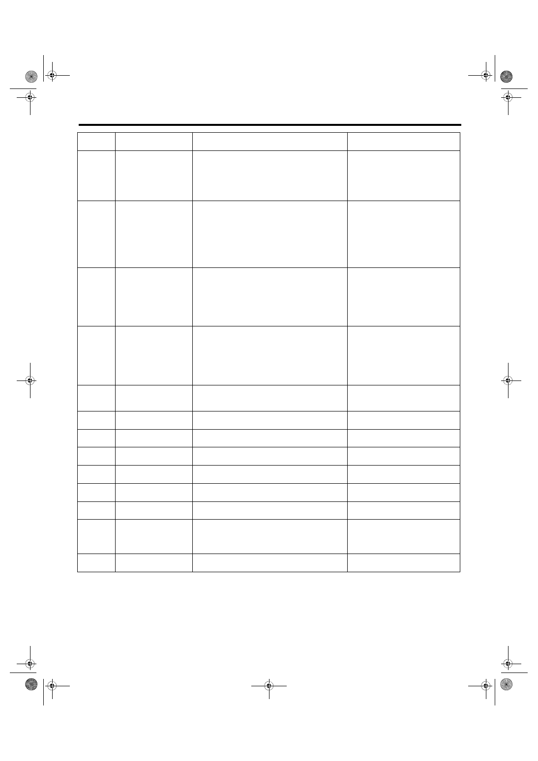
List of Cancel Code
CRUISE CONTROL SYSTEM (DIAGNOSTICS)
32
Cruse Control out of
Range
• Controlled vehicle speed decreased under the
limit during cruising.
• Set operation was performed at vehicle speed
unavailable for setting.
• RESUME operation was performed without
memorized vehicle speed.
34
Prohibition of cruise
control at continuing big
Accel. angle
The vehicle has been driven at higher speed than
set vehicle speed for an abnormally long time
(approximately 10 minutes) during cruise driving.
35
Prohibition of cruise
control at vehicle speed
F/B malfunction
Set vehicle speed cannot be kept because of some
reasons (steep uphill, parking brake, abnormal
decrease of engine output, etc.) during cruise driv-
ing.
41
VDC/TCS Operating
Vehicle dynamics control (VDC) or TCS is oper-
ated during cruise driving or cruise setting.
43
ABS/VDC Failure
ABS or Vehicle dynamics control (VDC) system
malfunction is detected during cruise driving or
cruise setting.
<Ref. to CC(diag)-24, 43, Diagnostic
Procedure with Cancel Code.>
44
Body Integrated unit
Failure
Body integrated unit system malfunction is
detected during cruise driving or cruise setting.
<Ref. to CC(diag)-24, 44, Diagnostic
Procedure with Cancel Code.>
45
Meter Failure
Combination meter malfunction is detected during
cruise driving or cruise setting.
<Ref. to CC(diag)-24, 45, Diagnostic
Procedure with Cancel Code.>
61
Brake switch abnormal
Malfunction in the stop light & brake switch is
detected.
<Ref. to CC(diag)-24, 61, Diagnostic
Procedure with Cancel Code.>
62
Neutral Switch Failure
Neutral position switch malfunction is detected.
<Ref. to CC(diag)-24, 62, Diagnostic
Procedure with Cancel Code.>
63
Abnormality of change
in vehicle speed
Malfunction of vehicle speed signal variation is
detected.
<Ref. to CC(diag)-25, 63, Diagnostic
Procedure with Cancel Code.>
64
Engine Sensor Failure 1 Malfunction related to engine is detected.
<Ref. to CC(diag)-25, 64, Diagnostic
Procedure with Cancel Code.>
65
Abnormality 1 of
switches related to
cruise control
Cruise control command switch malfunction is
detected. (When the switch is pressed ON for a
long time (approximately two minutes), stuck ON
condition is detected.)
<Ref. to CC(diag)-25, 65, Diagnostic
Procedure with Cancel Code.>
66
Cruise Control Calcula-
tion Error
Cruise control calculation (microcomputer) mal-
function is detected.
<Ref. to CC(diag)-25, 66, Diagnostic
Procedure with Cancel Code.>
Cancel
code
Item
Contents of diagnosis
Note
CC(diag)-14
Diagnostic Procedure with Cancel Code
CRUISE CONTROL SYSTEM (DIAGNOSTICS)
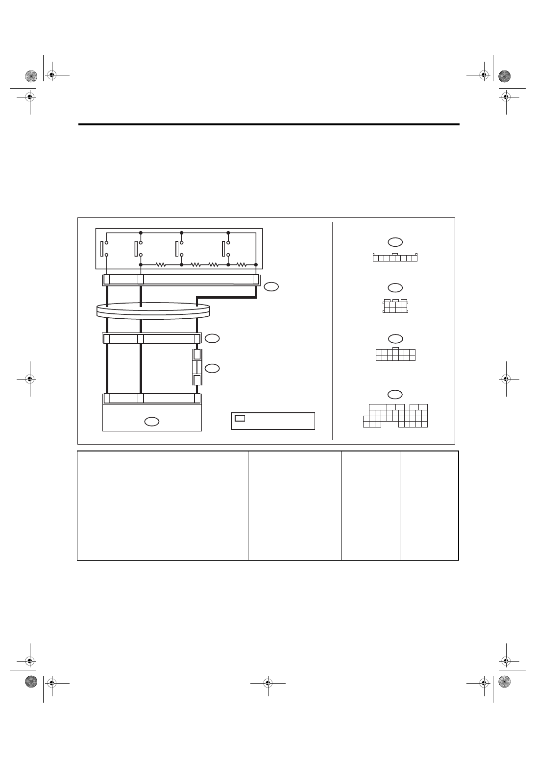
8. Diagnostic Procedure with Cancel Code
A: 11
Detected when main switch is pressed or when main switch related malfunction occurs.
TROUBLE SYMPTOM:
• Cruise control cannot be set. (Cancelled immediately.)
• Cruise control cannot be released.
WIRING DIAGRAM:
Cruise Control System <Ref. to WI-163, WIRING DIAGRAM, Cruise Control System.>
Step
Check
Yes
No
1
CHECK CRUISE CONTROL COMMAND
SWITCH CIRCUIT.
1) Remove the driver’s airbag module. <Ref. to
AB-15, REMOVAL, Driver’s Airbag Module.>
2) Disconnect the harness connector of cruise
control command switch.
3) Turn the ignition switch to ON.
4) Measure the voltage between harness con-
nector terminal and chassis ground.
Connector & terminal
(ST3) No. 8 (+) — Chassis ground (–):
(ST3) No. 7 (+) — Chassis ground (–):
Is the voltage 5 V or more?
Check the harness
between cruise
control command
switch and ECM,
and the steering
roll connector for
open or short cir-
cuit, or for poor
contact.
ECM
12
4
1 2 3
5 6 7 8
B122
ST3
4
1 2 3
5 6 7 8
B68
4
1 2 3
9 10 11 12 13 14
5 6 7
8
*
B122
*
*
13
11
10
4
8
7
B68
6
4
B136
ST3
B136
9
0
3
9
2
28
32
1
3
0
2
9
1
2
2
8
1
1
2
0
1
2
1
1
1
4
1
4
2
4
3
3
3
7
2
6
2
6
1
1
2
3
4
5
6
3
1
3
2
5
1
5
2
8
7
7
1
5
3
CC-00837
SET/COAST
SWITCH
RESUME/
ACCEL
SWITCH
CANCEL
SWITCH
MAIN
SWITCH
CRUISE CONTROL
COMMAND SWITCH
STEERING ROLL
CONNECTOR
: TERMINAL No. OPTIONAL
ARRANGEMENT
CC(diag)-15
Diagnostic Procedure with Cancel Code
CRUISE CONTROL SYSTEM (DIAGNOSTICS)
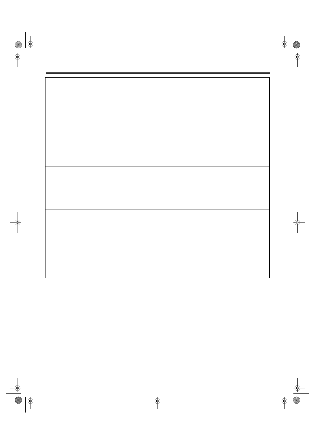
2
CHECK CRUISE CONTROL COMMAND
SWITCH CIRCUIT.
1) Turn the ignition switch to OFF.
2) Remove the cruise control command
switch. <Ref. to CC-6, REMOVAL, Cruise Con-
trol Command Switch.>
3) Measure the resistance between harness
connector terminal and chassis ground.
Connector & terminal
(ST3) No. 6 — Chassis ground:
Is the resistance less than 10
Ω?
Check for open cir-
cuit between
cruise control com-
mand switch,
ECM, and chassis
ground and check
the ECM.
3
CHECK CRUISE CONTROL COMMAND
SWITCH.
Measure the resistance between switch termi-
nals when the cruise control command switch is
not depressed.
Terminals
No. 6 — No. 7:
Is the resistance approx. 4 kΩ? Go to step
Replace the cruise
control command
switch. <Ref. to
CC-6, Cruise Con-
trol Command
Switch.>
4
CHECK CANCEL SWITCH.
1) Turn the ignition switch to OFF.
2) Remove the cruise control command
switch. <Ref. to CC-6, REMOVAL, Cruise Con-
trol Command Switch.>
3) Measure the resistance between switch ter-
minals with the CANCEL switch pressed.
Terminals
No. 6 — No. 7:
Is the resistance approx. less
than 1 Ω when the CANCEL
switch is pressed?
Replace the cruise
control command
switch. <Ref. to
CC-6, Cruise Con-
trol Command
Switch.>
5
CHECK SET/COAST SWITCH.
Measure the resistance between switch termi-
nals with the SET/COAST switch pressed.
Terminals
No. 6 — No. 7:
Is the resistance approx. 250 Ω
when SET/COAST switch is
pressed?
Replace the cruise
control command
switch. <Ref. to
CC-6, Cruise Con-
trol Command
Switch.>
6
CHECK RESUME/ACCEL SWITCH CIRCUIT.
Measure the resistance between switch termi-
nals with the RESUME/ACCEL switch pressed.
Terminals
No. 6 — No. 7:
Is the resistance approx. 1,500
Ω when RESUME/ACCEL
switch is pressed?
Replace the cruise
control command
switch. <Ref. to
CC-6, Cruise Con-
trol Command
Switch.>
Step
Check
Yes
No
CC(diag)-16
Diagnostic Procedure with Cancel Code
CRUISE CONTROL SYSTEM (DIAGNOSTICS)
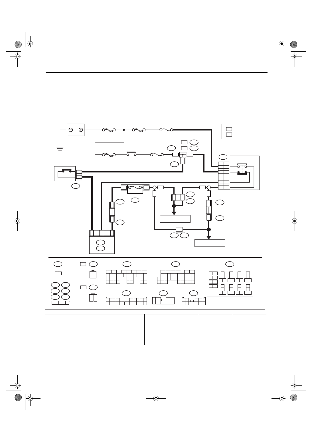
B: 12
Detected when brake pedal is depressed or malfunction related to stop light & brake switch occurs.
TROUBLE SYMPTOM:
• Cruise control cannot be set.
• Cruise control cannot be released.
WIRING DIAGRAM:
Cruise Control System <Ref. to WI-163, WIRING DIAGRAM, Cruise Control System.>
Step
Check
Yes
No
1
CHECK STOP LIGHT & BRAKE SWITCH.
Check the stop light & brake switch. <Ref. to
CC-9, Stop Light & Brake Switch.>
Is the stop light & brake switch
and installation position OK?
Replace the stop
light & brake
switch. Or adjust
the installation
position.
ECM
R168
B:
1 2 3 4
5 6 7 8 9
10 11 12 13 14 15 16 17 18 19 20
1 2 3 4 5
B442
B445
B441
B437
B440
B434
5Dr
B441
B440
B442
4Dr
B445
1
1
1
B99
1 2
3 4 5
6 7 8 9 10 11 12
F: B159
1
5
7
6
2
8
3 4
9
B437
B434
2
2
6
R3
B99
7
R168
B:
4Dr
4Dr
5Dr
5Dr
B159
F:
B15
7
F9
R3
B99
C15
B225
13
14
16
5
1
17
27
24
25
26
20
21
22
23
29
30
31
28
32 35
33
34
37
38
39
36
40
8
9
10
12
1
1
2
1
5
4
3
7
6
19
18
1 2
3 4
B65
4Dr
B65
1 2
3 4
5Dr
5Dr
4Dr
5Dr
4Dr
2
1
3
4
CC-00852
B225
2
1
B107
1 2
B107
1
2
B135
7
6
5
8
2
1
9
4
3
10
24 25
3
2
2
2
15
4
1
3
1
2
1
1
1
27
6
2
28
19
8
1
7
1
6
1
21
0
2
35
4
3
3
3
2
3
1
3
0
3
9
2
B:
B136
9
0
3
9
2
28
32
1
3
0
2
9
1
2
2
8
1
1
2
0
1
2
1
1
1
4
1
4
2
4
3
3
3
7
2
6
2
6
1
1
2
3
4
5
6
3
1
3
2
5
1
5
2
8
7
7
1
5
3
C:
C: B136
B: B135
B9
C3
2
1
3
4
B65
:
:
:
:
SBF-2
SBF-8
MAIN SBF
F/B No. 8
F/B No. 4
BATTERY
IGNITION
RELAY
STOP LIGHT
SWITCH &
BRAKE SWITCH
STOP LIGHT
SWITCH
BRAKE
SWITCH
RELAY BOX
7.5A
CLUTCH SWITCH
: 4 DOOR MODEL
: 5 DOOR MODEL
FUSE &
RELAY
BOX (F/B)
REF. TO
STOP LIGHT SYSTEM
REF. TO
STOP LIGHT SYSTEM
MULTI
JOINT
CONNECTOR
MUL
TI
JOINT
CONNECT
OR
Нет комментариевНе стесняйтесь поделиться с нами вашим ценным мнением.
Текст