Subaru Impreza 3 / Impreza WRX / Impreza WRX STI. Service manual — part 761
CC(diag)-5
Electrical Component Location
CRUISE CONTROL SYSTEM (DIAGNOSTICS)
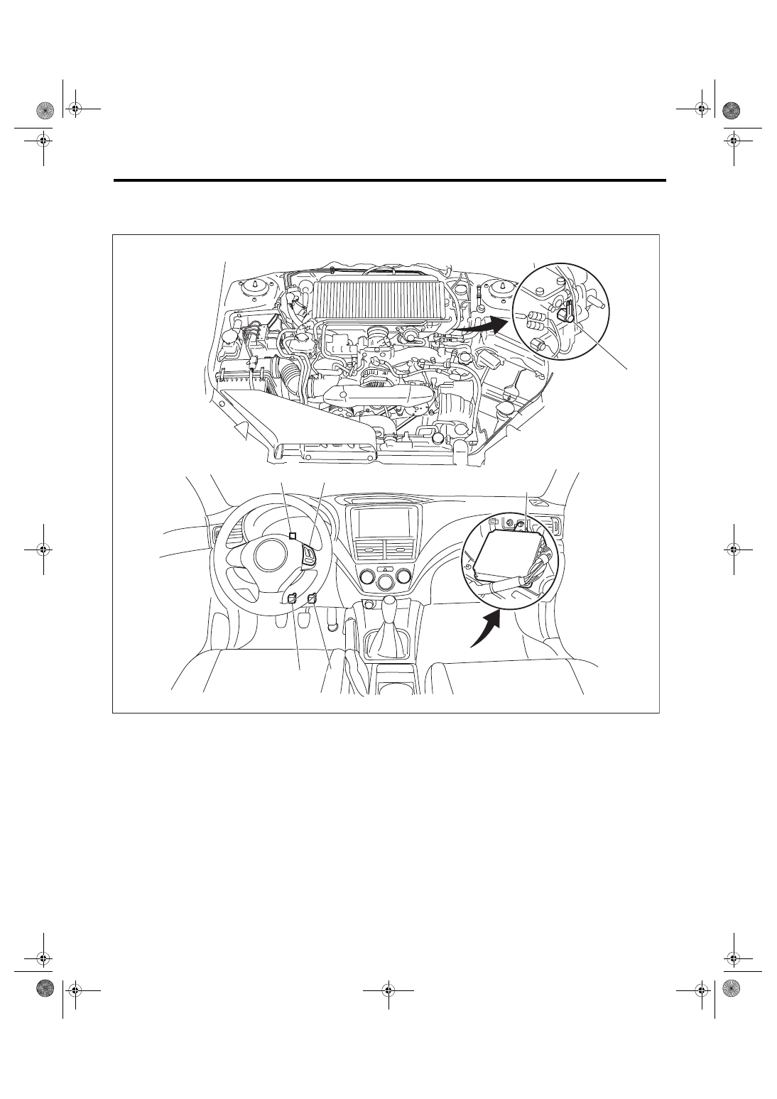
3. Electrical Component Location
A: LOCATION
(1)
Engine control module (ECM)
(3)
Stop light and brake switch
(5)
Neutral position switch
(2)
Cruise control command switch
(4)
Cruise indicator light and cruise
set indicator light
(6)
Clutch switch
(6)
(3)
(4)
(1)
(2)
CC-00851
(5)
CC(diag)-6
Engine Control Module (ECM) I/O Signal
CRUISE CONTROL SYSTEM (DIAGNOSTICS)
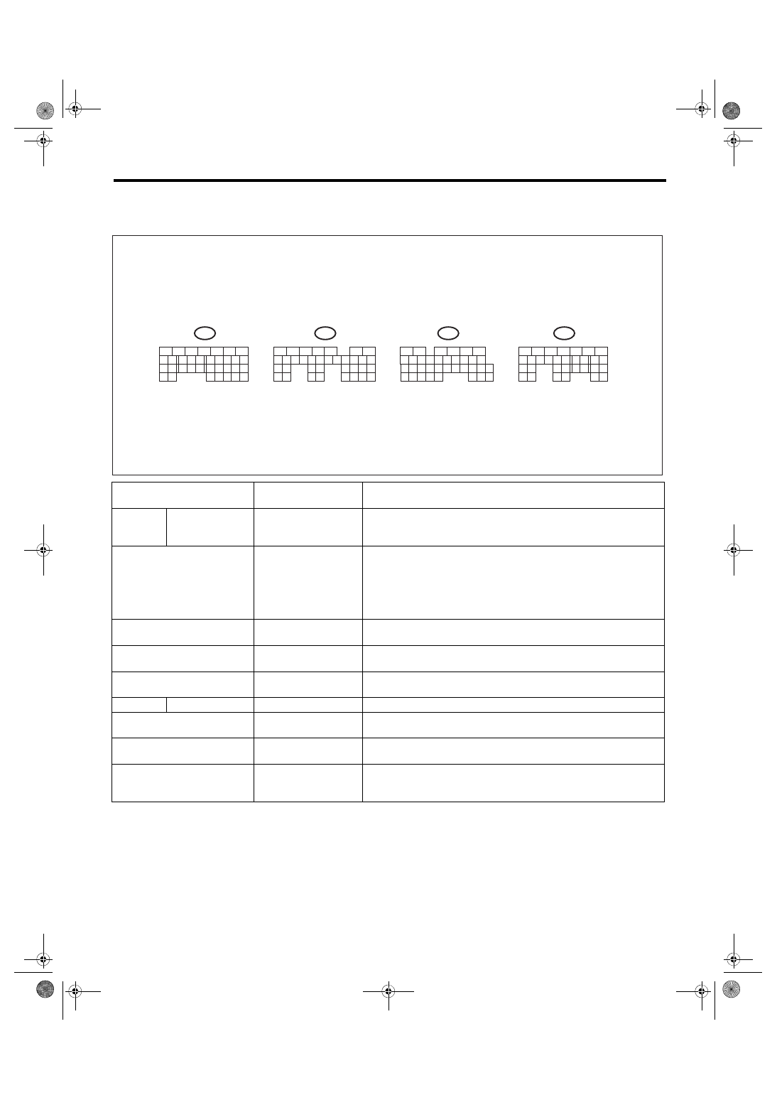
4. Engine Control Module (ECM) I/O Signal
A: ELECTRICAL SPECIFICATION
B: WIRING DIAGRAM
<Ref. to WI-163, WIRING DIAGRAM, Cruise Control System.>
Content
Terminal No.
Measurement condition and I/O signal
(Idling with ignition ON: except for cruise set light)
Main
power
supply
VB (CONTROL 1)
VB (CONTROL 2)
C1
D7
• Battery voltage is detected when the main power is turned ON.
• “0 V” is detected when the main power is turned OFF.
Command switch
C12
• “0 V” is detected when the command switch is in CANCEL position.
• “Approx. 1 V” is detected when the command switch is in SET/
COAST position.
• “Approx. 3 V” is detected when the command switch is in RESUME/
ACCEL position.
• “Approx. 4 V” is detected when the command switch is released.
Brake switch 1
(brake switch)
C15
• Battery voltage is detected when the brake pedal is released.
• “0 V” is detected when brake pedal is depressed.
Brake switch 2
(stop light switch)
C3
• Battery voltage is detected when brake pedal is depressed.
• “0 V” is detected when the brake pedal is released.
Main switch
C13
• “0 V” is detected while the main switch is pressed or turned ON.
• Approx. “5 V” is detected when the main switch is OFF.
Ground
GND (CONTROL)
A6
—
Ignition switch
C30
• Battery voltage is detected when the ignition switch is turned ON.
• “0 V” is detected when the ignition switch is turned OFF.
Clutch switch
B9
• “0 V” is detected when clutch pedal is depressed.
• Battery voltage is detected when the clutch pedal is released.
Neutral position switch
C35
• Battery voltage is detected when the shift lever is in any position
except for neutral.
• “Approx. 0 V” is detected when the shift lever is in neutral position.
CC-00197
B134
9
30 29 28
32 31
20 19 18
22 21
10
12 11
14
24
34 33
27 26
17 16
1
2
3
4
5
6
7
13
23
15
25
8
B135
9
30 29 28
32
31
20
22 21
10
12 11
14
24
35
33
27 26
17 16
1
2
3
4
5
6
7
13
23
15
25
8
B136
9
30 29 28
32 31
20 19 18
22 21
10
12 11
14
24
34 33
27 26
16
1
2
3
4
5
6
13
23
15
25
8
B137
9
29 28
20 19 18
22 21
10
12 11
14
24
17 16
1
2
3
4
5
6
7
13
23
15
25
8
18
19
34
7
17
35
30
31
27 26
TO D:
TO C:
TO B:
TO A:
CC(diag)-7
Subaru Select Monitor
CRUISE CONTROL SYSTEM (DIAGNOSTICS)
5. Subaru Select Monitor
A: OPERATION
1. GENERAL DESCRIPTION
The on-board diagnosis function of the cruise con-
trol system uses Subaru Select Monitor.
The on-board diagnosis function operates in two
categories, which are used depending on the type
of problems;
1) Cruise Control Cancel Conditions Diagnosis:
(1) This category of diagnosis requires actual
vehicle driving in order to determine the cause,
as when cruise speed is cancelled during driv-
ing although cruise cancel condition is not en-
tered.
(2) Cruise control memory in ECM stores the
cancel code which occurred during driving.
When there are multiple cancel code, they are
shown on the Subaru Select Monitor.
CAUTION:
• The cruise control memory stores not only
the cruise “cancel” which occurred (although
“cancel” operation is not entered by the driver),
but also the “cancel” condition input by the
driver.
• The latest memory content (latest code) is
cleared when ignition switch is turned to OFF.
However, memory contents set by the diagno-
sis of faulty switches related to the system and
cruise control will remain as trouble history
(memory code) after the ignition switch is
turned to OFF.
2) Real-time Diagnosis:
Real-time diagnosis function is used to determine
whether or not the input signal system is in good or-
der, according to signal emitted from switches, sen-
sors, etc.
(1) Vehicle cannot be driven at cruise speed
when the problem occurs in the cruise control
system or relevant circuits.
(2) Monitor the signal conditions from switches
and sensors.
2. CRUISE CONTROL CANCEL CONDI-
TIONS DIAGNOSIS
1) Prepare the Subaru Select Monitor kit.
2) Connect the diagnosis cable to Subaru Select
Monitor.
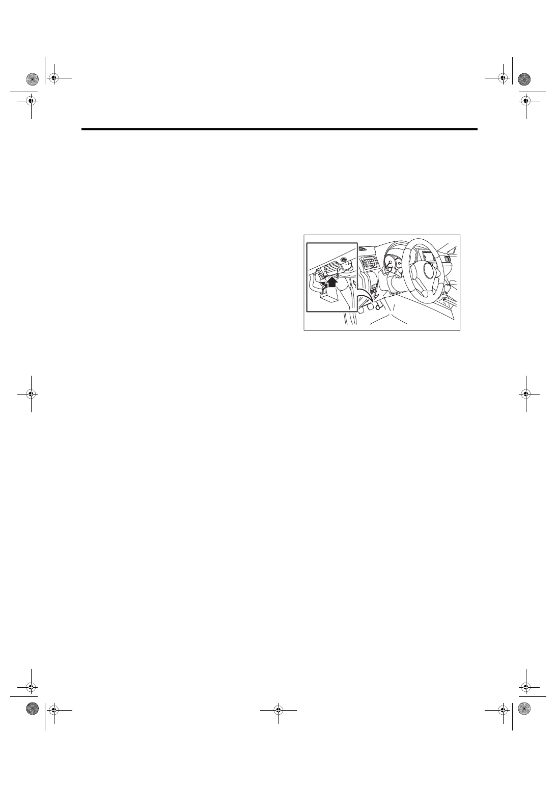
3) Connect the Subaru Select Monitor to data link
connector.
(1) Data link connector is located in the lower
portion of the instrument panel (on the driver’s
side).
(2) Connect the diagnosis cable to data link
connector.
4) Start the engine and turn the cruise control main
switch to ON.
5) Run the Subaru Select Monitor.
6) On «Main Menu» display, select {Each System
Check}.
On «System Selection Menu» display, select {En-
gine Control System} and select the [OK]. Select
[OK] after the engine type information is displayed.
7) Drive vehicle at 40 km/h (25 MPH) or more and
set the cruise control.
CAUTION:
• When performing diagnosis, observe the le-
gal speed limit on the road.
• The cancel code will be also appear when
cruise control is cancelled by the driver’s oper-
ation. Do not confuse them.
• Be sure to get an assistant to support the di-
agnosis while driving, and have him/her oper-
ate the select monitor.
CC-00653
CC(diag)-8
Subaru Select Monitor
CRUISE CONTROL SYSTEM (DIAGNOSTICS)
8) When the set speed is cancelled by itself (with-
out any cancel operations such as applying brake)
or when the cruise control could not be set by per-
forming the setting operation, selecting the {Cancel
Code(s) Display} on the engine malfunction diag-
nosis screen will display the cancel code on the se-
lect monitor display.
NOTE:
The {Latest Diagnostic Code(s)} and {Memorized
Diagnostic Code(s)} are contained in the cancel
code. The latest code recognized during current
test drive is displayed in {Latest Diagnostic
Code(s)}. Cancel codes resulting from fault diagno-
sis of switches relating to the system and cruise
control are also displayed in {Memorized Diagnos-
tic Code(s)}.
9) Perform Engine DTC Clear Memory operation.
<Ref. to EN(H4DOTC)(diag)-63, OPERATION,
Cancel codes for switches relating to the system
and cruise control are deleted by clearing memory
on the engine side.
NOTE:
The latest code will be cleared by turning ignition
switch to OFF.
3. REAL-TIME DIAGNOSIS
1) Connect the Subaru Select Monitor.
2) Turn the ignition switch and cruise control main
switch to ON.
3) Run the Subaru Select Monitor.
4) On «Main Menu» display, select {Each System
Check}.
5) On «System Selection Menu» display, select
{Engine Control System}.
6) Select [OK] after engine type information is dis-
played.
7) On «Cruise Control Diagnosis» display, select
{Current Data Display & Save}.
8) Make sure that normal display is shown when
operated as follows:
• Depress and release the brake pedal. (Stop light
switch and brake switch are turned ON.)
• Turn the main switch to ON.
• Turn the “CANCEL” switch to ON.
• Turn the “SET/COAST” switch to ON.
• Turn the “RESUME/ACCEL” switch to ON.
• Depress or release the clutch pedal.
• Place the shift lever in any position other than
neutral.
NOTE:
• For details concerning the operation procedure,
refer to “PC application help for Subaru Select
Monitor”.
• For detailed concerning cancel codes, refer to
Нет комментариевНе стесняйтесь поделиться с нами вашим ценным мнением.
Текст