Subaru Impreza 3 / Impreza WRX / Impreza WRX STI. Service manual — part 764
CC(diag)-17
Diagnostic Procedure with Cancel Code
CRUISE CONTROL SYSTEM (DIAGNOSTICS)
2
CHECK STOP LIGHT & BRAKE SWITCH
CIRCUIT.
1) Turn the ignition switch to OFF.
2) Disconnect the stop light & brake switch har-
ness connector.
3) Turn the ignition switch to ON.
4) Measure the voltage between harness con-
nector terminal and chassis ground.
Connector & terminal
5 door model:
(B65) No. 1 (+) — Chassis ground (–):
4 door model:
(B65) No. 3 (+) — Chassis ground (–):
Is the voltage 10 V or more?
• Check fuse No. 8
(in fuse & relay
box).
• Check for open
or short in the har-
ness between stop
light & brake switch
and fuse & relay
box.
3
CHECK STOP LIGHT & BRAKE SWITCH
CIRCUIT.
Measure the voltage between harness connec-
tor terminal and chassis ground.
Connector & terminal
5 door model:
(B65) No. 3 (+) — Chassis ground (–):
4 door model:
(B65) No. 1 (+) — Chassis ground (–):
Is the voltage 10 V or more?
• Check fuse No. 4
(in fuse & relay
box).
• Check for open
or short in the har-
ness between stop
light & brake switch
and fuse & relay
box.
4
CHECK STOP LIGHT & BRAKE SWITCH
CIRCUIT.
1) Turn the ignition switch to OFF.
2) Disconnect the harness connector of ECM.
3) Measure the resistance between ECM har-
ness connector terminal and stop light & brake
switch harness connector terminal.
Connector & terminal
5 door model:
(B136) No. 15 — (B65) No. 4:
(B136) No. 3 — (B65) No. 2:
4 door model:
(B136) No. 15 — (B65) No. 2:
(B136) No. 3 — (B65) No. 4:
Is the resistance less than 10
Ω?
Repair the har-
ness.
Step
Check
Yes
No
CC(diag)-18
Diagnostic Procedure with Cancel Code
CRUISE CONTROL SYSTEM (DIAGNOSTICS)
C: 13
Detected when clutch pedal is depressed or malfunction related to clutch switch occurs.
TROUBLE SYMPTOM:
• Cruise control cannot be set.
• Cruise control cannot be released.
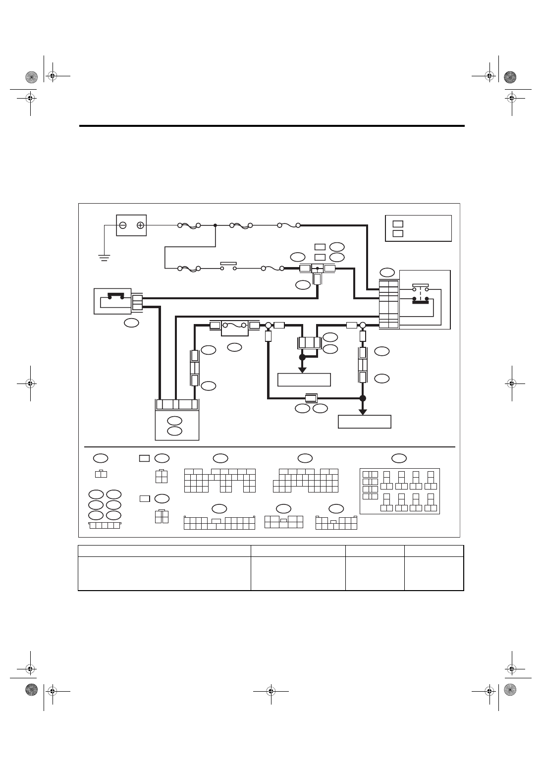
WIRING DIAGRAM:
Cruise Control System <Ref. to WI-163, WIRING DIAGRAM, Cruise Control System.>
Step
Check
Yes
No
1
CHECK CLUTCH SWITCH.
Check the clutch switch. <Ref. to CL-34,
INSPECTION, Clutch Switch.>
Is the clutch switch and installa-
tion position OK?
Replace the clutch
switch. Or adjust
the installation
position.
ECM
R168
B:
1 2 3 4
5 6 7 8 9
10 11 12 13 14 15 16 17 18 19 20
1 2 3 4 5
B442
B445
B441
B437
B440
B434
5Dr
B441
B440
B442
4Dr
B445
1
1
1
B99
1 2
3 4 5
6 7 8 9 10 11 12
F: B159
1
5
7
6
2
8
3 4
9
B437
B434
2
2
6
R3
B99
7
R168
B:
4Dr
4Dr
5Dr
5Dr
B159
F:
B15
7
F9
R3
B99
C15
B225
13
14
16
5
1
17
27
24
25
26
20
21
22
23
29
30
31
28
32 35
33
34
37
38
39
36
40
8
9
10
12
1
1
2
1
5
4
3
7
6
19
18
1 2
3 4
B65
4Dr
B65
1 2
3 4
5Dr
5Dr
4Dr
5Dr
4Dr
2
1
3
4
CC-00852
B225
2
1
B107
1 2
B107
1
2
B135
7
6
5
8
2
1
9
4
3
10
24 25
3
2
2
2
15
4
1
3
1
2
1
1
1
27
6
2
28
19
8
1
7
1
6
1
21
0
2
35
4
3
3
3
2
3
1
3
0
3
9
2
B:
B136
9
0
3
9
2
28
32
1
3
0
2
9
1
2
2
8
1
1
2
0
1
2
1
1
1
4
1
4
2
4
3
3
3
7
2
6
2
6
1
1
2
3
4
5
6
3
1
3
2
5
1
5
2
8
7
7
1
5
3
C:
C: B136
B: B135
B9
C3
2
1
3
4
B65
:
:
:
:
SBF-2
SBF-8
MAIN SBF
F/B No. 8
F/B No. 4
BATTERY
IGNITION
RELAY
STOP LIGHT
SWITCH &
BRAKE SWITCH
STOP LIGHT
SWITCH
BRAKE
SWITCH
RELAY BOX
7.5A
CLUTCH SWITCH
: 4 DOOR MODEL
: 5 DOOR MODEL
FUSE &
RELAY
BOX (F/B)
REF. TO
STOP LIGHT SYSTEM
REF. TO
STOP LIGHT SYSTEM
MULTI
JOINT
CONNECTOR
MUL
TI
JOINT
CONNECT
OR
CC(diag)-19
Diagnostic Procedure with Cancel Code
CRUISE CONTROL SYSTEM (DIAGNOSTICS)
2
CHECK CLUTCH SWITCH CIRCUIT.
1) Turn the ignition switch to OFF.
2) Disconnect the clutch switch harness con-
nector.
3) Turn the ignition switch to ON.
4) Measure the voltage between harness con-
nector terminal and chassis ground.
Connector & terminal
(B107) No. 1 (+) — Chassis ground (–):
Is the voltage 10 V or more?
• Check fuse No. 4
(in fuse & relay
box).
• Check open or
shorted circuit of
harness between
clutch switch and
fuse & relay box.
3
CHECK CLUTCH SWITCH CIRCUIT.
1) Turn the ignition switch to OFF.
2) Disconnect the harness connector of ECM.
3) Measure the resistance between clutch
switch harness connector terminal and ECM
harness connector terminal.
Connector & terminal
(B107) No. 2 — (B135) No. 9:
Is the resistance less than 10
Ω?
Repair the har-
ness.
Step
Check
Yes
No
CC(diag)-20
Diagnostic Procedure with Cancel Code
CRUISE CONTROL SYSTEM (DIAGNOSTICS)
D: 14
Detected when select lever is set in the neutral position, or when malfunction related to neutral position
switch occurs.
TROUBLE SYMPTOM:
Cruise control cannot be set.
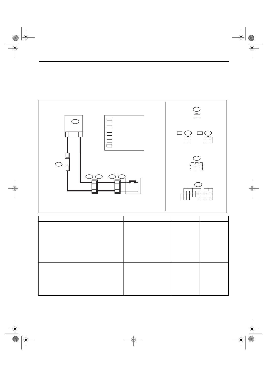
WIRING DIAGRAM:
Cruise Control System <Ref. to WI-163, WIRING DIAGRAM, Cruise Control System.>
Step
Check
Yes
No
1
CHECK NEUTRAL POSITION SWITCH CIR-
CUIT.
1) Turn the ignition switch to OFF.
2) Disconnect the neutral position switch har-
ness connector.
3) Turn the ignition switch to ON.
4) Measure the voltage between harness con-
nector terminal and chassis ground.
Connector & terminal
(T12) No. 1 (+) — Chassis ground (–):
Is the voltage 10 V or more?
Check for open or
short in the har-
ness between neu-
tral position switch
and ECM.
2
CHECK NEUTRAL POSITION SWITCH CIR-
CUIT.
1) Turn the ignition switch to OFF.
2) Measure resistance between harness con-
nector terminal of neutral position switch and
chassis ground.
Connector & terminal
(T12) No. 2 — Chassis ground:
Is the resistance less than 10
Ω?
Repair the har-
ness.
ECM
B128
1 2
3 4
B128
1
3
4 5 6
2
:
:
*
3
*
2
*
1
*
1
*
2
*
3
*
3
C: B136
5
3
4
3
3
3
6
2
7
2
6
5
4
3
2
1
1
3
2
3
9
2
3
2
2
2
1
2
8
2
0
2
9
1
8
1
7
1
7 8 9
0
3
4
2
5
2
5
1
4
1
3
1
2
1
1
1
0
1
6
1
T12
2
1
B122
3 4
7 8
1 2
5 6
B136
C:
C35
C4
T9
B128
T2
1
2
T12
B122
CC-00853
SI
ES
SI
ES
JOINT
CONNECTOR
NEUTRAL
POSITION SWITCH
: WITH SI-DRIVE
: WITHOUT SI-DRIVE
: WITHOUT SI-DRIVE : 1
WITH SI-DRIVE : 2
: WITHOUT SI-DRIVE : 3
WITH SI-DRIVE : 5
: TERMINAL No. OPTIONAL
ARRANGEMENT
Нет комментариевНе стесняйтесь поделиться с нами вашим ценным мнением.
Текст