Subaru Impreza 3 / Impreza WRX / Impreza WRX STI. Service manual — part 443
6MT-109
Shifter Fork and Rod
MANUAL TRANSMISSION AND DIFFERENTIAL
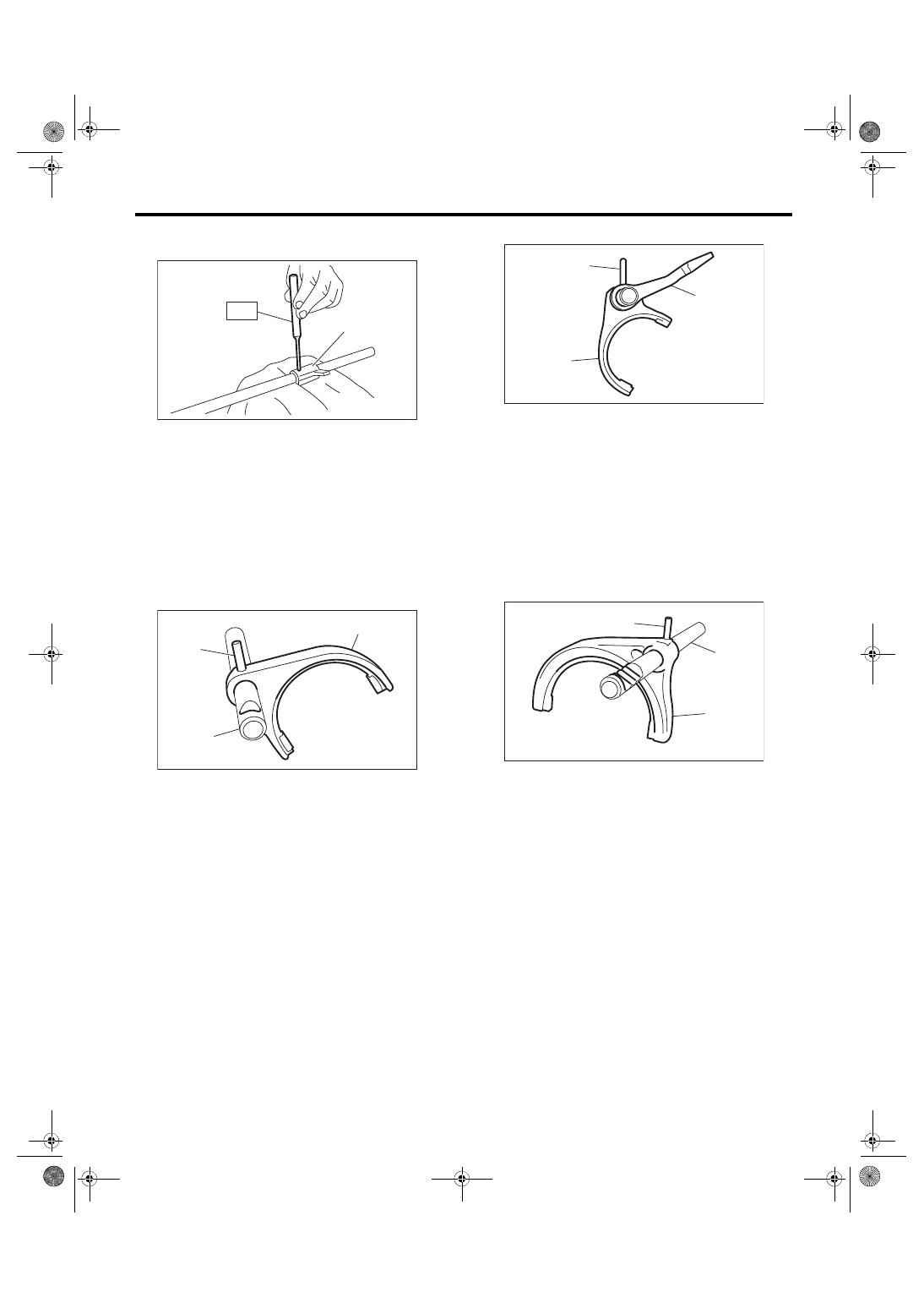
3) Remove the interlock arm using the ST.
ST 398791700
REMOVER
D: ASSEMBLY
1. REVERSE SHIFTER FORK
1) Using the ST, install the reverse fork.
ST 398791700
REMOVER
NOTE:
• Confirm that the reverse fork and rod are in-
stalled in the proper direction.
• Use a new straight pin.
2) Using the ST, install the reverse arm.
ST 398791700
REMOVER
NOTE:
• Confirm that the reverse arm and rod are in-
stalled in the proper direction.
• Use a new straight pin.
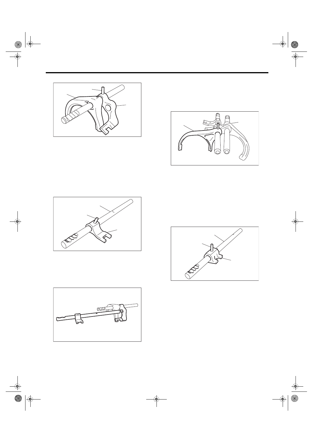
2. 1ST-2ND, 3RD-4TH SHIFTER FORK
1) Using the ST, install the 1st-2nd shifter fork.
ST 398791700
REMOVER
NOTE:
• Make sure that the 1st-2nd shifter fork and rod
are installed in the correct direction.
• Use a new straight pin.
2) Using the ST, install the 1st-2nd shifter arm.
ST 398791700
REMOVER
NOTE:
• Make sure that the 1st-2nd shifter arm and fork
are installed in the correct direction.
(A) Interlock arm
(A) Reverse fork
(B) Reverse rod
(C) Straight pin
MT-00690
(A)
ST
MT-00691
(C)
(B)
(A)
(A) Reverse arm
(B) Reverse rod
(C) Straight pin
(A) 1st-2nd shifter fork
(B) 1st-2nd shifter rod
(C) Straight pin
MT-00692
(C)
(B)
(A)
MT-00693
(C)
(B)
(A)
6MT-110
Shifter Fork and Rod
MANUAL TRANSMISSION AND DIFFERENTIAL
• Use a new straight pin.
3) Using the ST, install the 3rd-4th shifter arm.
ST 398791700
REMOVER
NOTE:
• Make sure that the 3rd-4th shifter arm and rod
are installed in the correct direction.
• Use a new straight pin.
4) Attach the 3rd-4th fork rod to the 1st-2nd shifter
arm.
5) Using the ST, install the 3rd-4th shifter fork.
ST 398791700
REMOVER
NOTE:
• Make sure that the 3rd-4th shifter fork is installed
in the correct direction.
• Use a new straight pin.
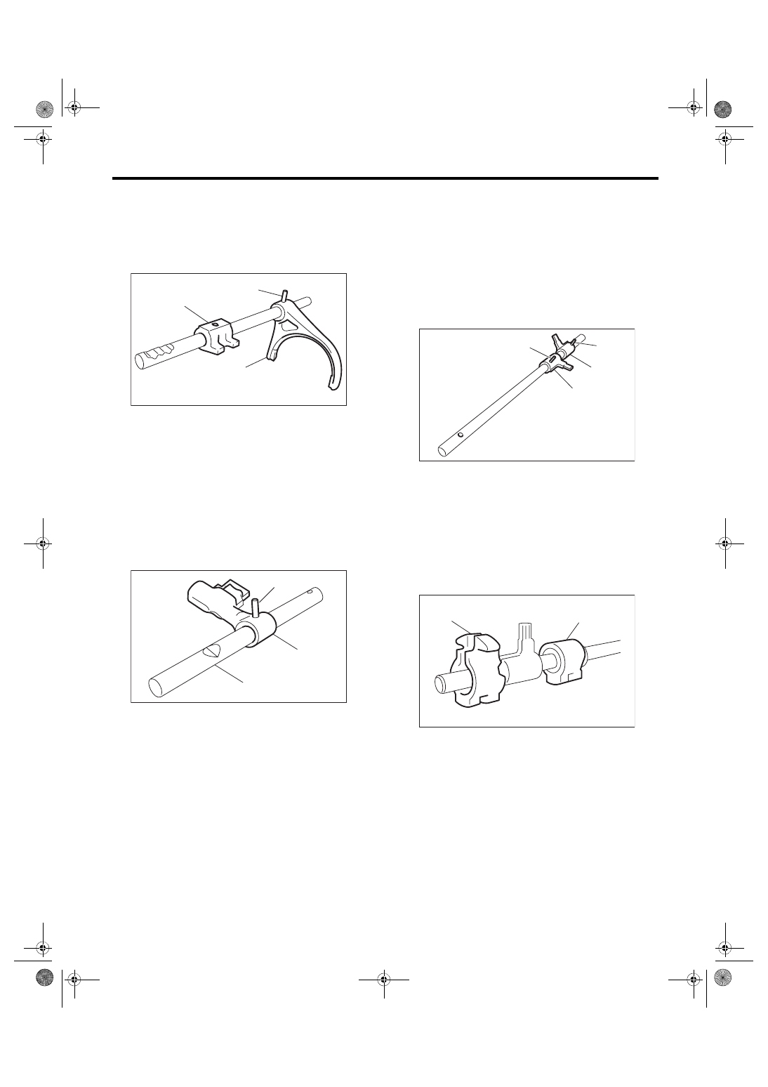
3. 5TH-6TH SHIFTER FORK
1) Using the ST, install the 5th-6th shifter arm.
ST 398791700
REMOVER
NOTE:
• Make sure that the 5th-6th shifter arm and rod
are installed in the correct direction.
• Use a new straight pin.
(A) 1st-2nd shifter fork
(B) 1st-2nd shifter arm
(C) Straight pin
(A) 3rd-4th shifter rod
(B) 3rd-4th shifter arm
(C) Straight pin
MT-00694
(C)
(B)
(A)
MT-00695
(C)
(B)
(A)
MT-00696
(A) 3rd-4th shifter fork
(B) Straight pin
(A) 5th-6th shifter arm
(B) 5th-6th shifter rod
(C) Straight pin
MT-01737
(B)
(A)
MT-00698
(C)
(B)
(A)
6MT-111
Shifter Fork and Rod
MANUAL TRANSMISSION AND DIFFERENTIAL
2) Using the ST, install the 5th-6th shifter fork.
ST 398791700
REMOVER
NOTE:
• Check that the 5th-6th shifter fork and arm are in-
stalled.
• Use a new straight pin.
4. SHIFTER ARM SHAFT
Using the ST, install the selector arm.
ST 398791700
REMOVER
NOTE:
• Confirm that the selector arm and rod are in-
stalled in the proper direction.
• Use a new straight pin.
5. STRIKING ROD
1) Using the ST, install the reverse interlock arm
and interlock arm.
ST 398791700
REMOVER
NOTE:
• Confirm that the reverse interlock arm and rod
are installed in the proper direction.
• Confirm that the interlock arm and rod are in-
stalled in the proper direction.
• Use a new straight pin.
2) Attach the reverse interlock block and interlock
block to the striking rod.
NOTE:
Confirm that the reverse interlock block and inter-
lock block are installed in the proper direction.
E: INSPECTION
1) Check the shift shaft and shift rod for damage.
Replace if damaged.
2) Repair or replace the gearshift mechanism if ex-
cessively worn, bent or defective in any way.
(A) 5th-6th shifter fork
(B) 5th-6th shifter arm
(C) Straight pin
(A) Selector rod
(B) Selector arm
(C) Straight pin
MT-00699
(C)
(B)
(A)
MT-01096
(B)
(A)
(C)
(A) Reverse interlock arm
(B) Interlock arm
(C) Straight pin
(A) Reverse interlock block
(B) Interlock block
MT-00701
(C)
(C)
(B)
(A)
MT-00688
(A)
(B)
6MT-112
Shifter Fork and Rod
MANUAL TRANSMISSION AND DIFFERENTIAL
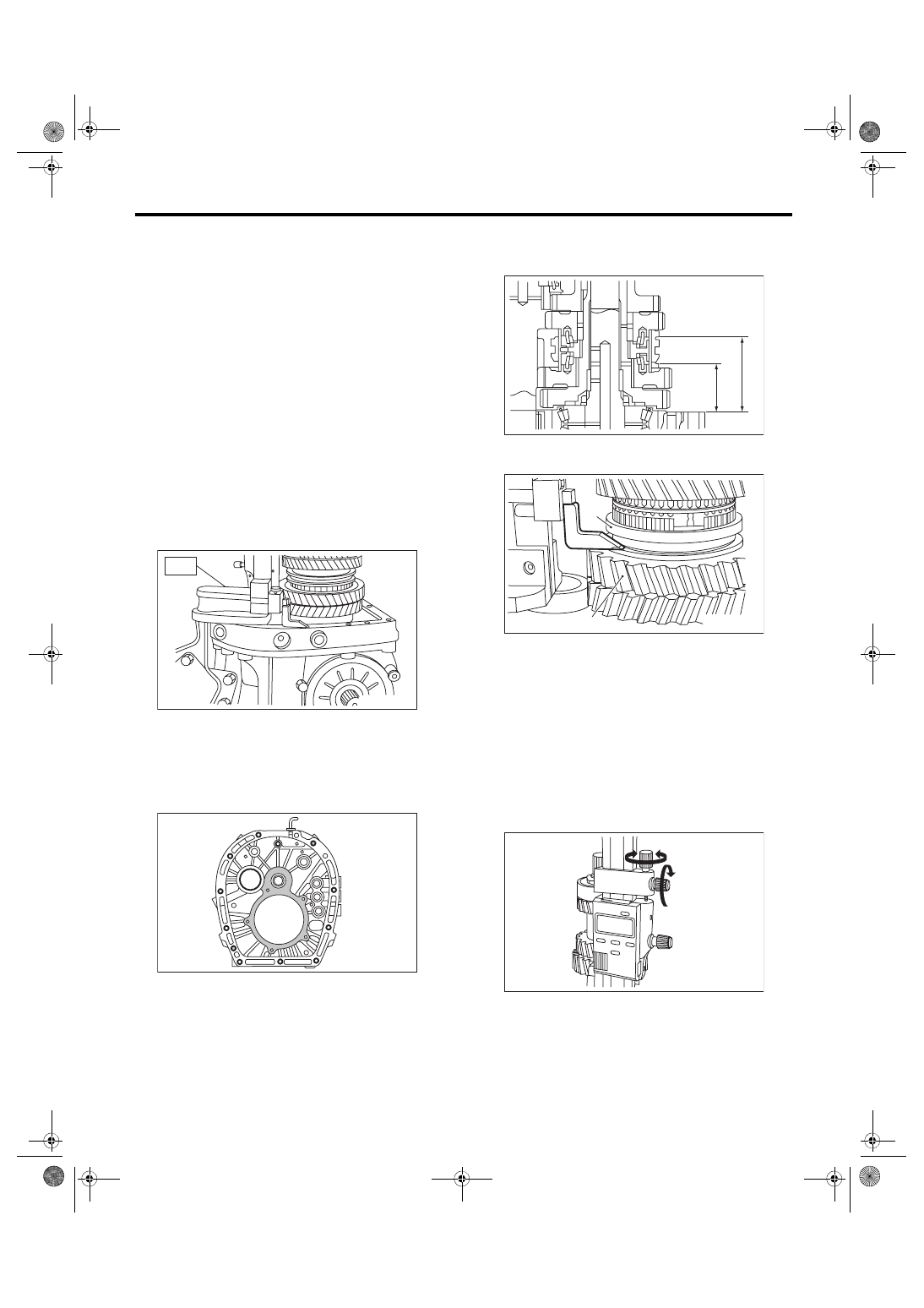
F: ADJUSTMENT
1. 1ST-2ND FORK ROD SELECTION
NOTE:
In the following conditions, perform the procedures
below.
• Replacement of the 1st and 2nd driven gear
• 1st and 2nd synchro ring assembly replacement
• Adapter plate replacement
• Driven shaft replacement
• 1st-2nd hub and sleeve assembly replacement.
1) Insert the drive pinion assembly into the adapter
plate.
NOTE:
Confirm that the thrust bearing outer race has not
been removed and the drive pinion is not lifted.
2) Set the height gauge to the adapter plate. Lower
the height gauge indicator to the mating surface of
the adapter plate and case, and set to zero points.
ST 18853AA000 HEIGHT GAUGE
NOTE:
• The adapter plate will be the base point for the
measurement. Use a scraper to remove any gasket
material remaining on the end face.
• During measurement, do not place the height
gauge in the shaded area shown in the figure.
3) Select the main shaft snap ring. <Ref. to 6MT-
77, ADJUSTMENT, Main Shaft Assembly.>
4) Measure “B1” and “B2” as shown in the figure.
5) Shift down the 1st-2nd sleeve all the way to the
1st driven gear side, and measure “B1”.
NOTE:
• Set the height gauge indicator near the measure-
ment target, and lock dial (1) as shown in the figure.
Turn dial (2), and set the indicator to the 1st side
end surface of the sleeve.
• Turn approximately 72° at a time, and measure
the sleeve in 5 locations. Round down the 2 highest
and 2 lowest measurement values. The remaining
center value is used as the measurement value.
MT-00582
ST
MT-00583
(A) 1st driven gear
(B) 1st-2nd sleeve
MT-00979
B1
B2
MT-00702
(A)
(B)
MT-00585
(2)
(1)
Нет комментариевНе стесняйтесь поделиться с нами вашим ценным мнением.
Текст