Subaru Impreza 3 / Impreza WRX / Impreza WRX STI. Service manual — part 171
ME(w/o STI)-65
Camshaft
MECHANICAL
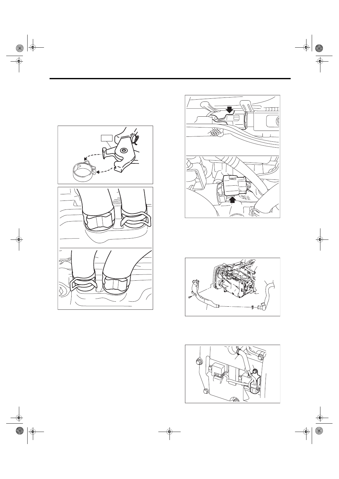
11) Connect the PCV hose (A) and PCV hose as-
sembly (B) to the rocker cover.
NOTE:
Use a new clamp for the PCV hose (A), fit the cut
out in the ST with the protrusion on the clamp as
shown in the figure, and lock the clamp.
ST 18353AA000 CLAMP PLIERS
12) Connect the connector to oil flow control sole-
noid valve.
13) Install the ignition coil. <Ref. to IG(w/o STI)-8,
14) Install the air duct B (B) to the rocker cover LH
and the air duct A (A).
Tightening torque:
6.4 N·m (0.7 kgf-m, 4.7 ft-lb)
15) Securely install the engine harness with clip (A)
and stay (B) to the rocker cover RH.
Tightening torque:
6.4 N·m (0.7 kgf-m, 4.7 ft-lb)
ME-04374
ST
ME-05768
(A)
(B)
(A)
(B)
ME-05977
ME-04965
(B)
(A)
ME-04652
(A)
(B)
ME(w/o STI)-66
Camshaft
MECHANICAL
16) Install the timing belt cover. <Ref. to ME(w/o
STI)-47, INSTALLATION, Timing Belt Cover.>
17) Install the crank pulley. <Ref. to ME(w/o STI)-
45, INSTALLATION, Crank Pulley.>
18) Install the rear side belt. <Ref. to ME(w/o STI)-
39, REAR SIDE BELT, INSTALLATION, V-belt.>
19) Install the engine to the vehicle. <Ref. to ME(w/
o STI)-33, INSTALLATION, Engine Assembly.>
C: INSPECTION
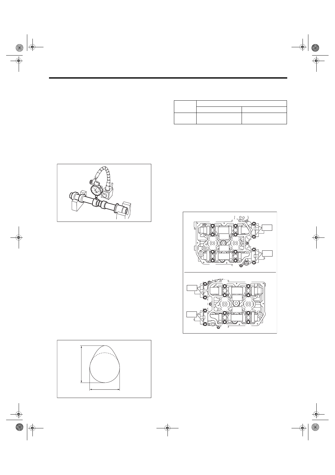
1) Measure the bend, and repair or replace if nec-
essary.
Camshaft bend limit:
0.020 mm (0.00079 in)
2) Check the journal for damage and wear. Re-
place if faulty.
3) Check the cutout portion used for camshaft sen-
sor for damage. Replace if faulty.
4) Check the cam face condition, and remove the
minor faults by grinding with oil stone. If offset wear
occurs, replace it.
5) Measure the cam lobe height “H” and cam base
circle diameter “A”. If it exceeds the standard or off-
set wear occurs, replace it.
Cam lobe height H:
Standard
Intake
46.55 — 46.65 mm (1.833 — 1.837 in)
Exhaust
46.75 — 46.85 mm (1.841 — 1.844 in)
Cam base circle diameter A:
Standard
37.0 mm (1.457 in)
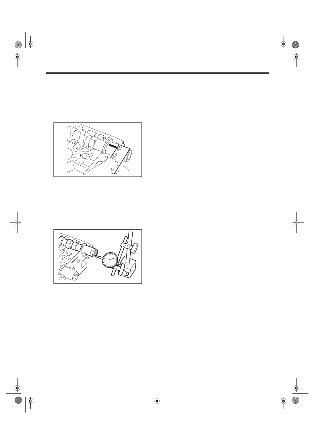
6) Measure the outside diameter of camshaft jour-
nal. If the journal diameter is not within specifica-
tion, check the oil clearance.
7) Measure the oil clearance of camshaft journal.
(1) Clean the camshaft cap and cylinder head
camshaft journal.
(2) Place the camshaft on cylinder head. (With-
out installing the valve lifter)
(3) Place a plastigauge across each camshaft
journals.
(4) Gradually tighten the camshaft cap in at
least two steps, in alphabetical order shown in
the figure, and then tighten to the specified
torque. Do not turn the camshaft.
Tightening torque:
T1: 9.75 N·m (1.0 kgf-m, 7.2 ft-lb)
T2: 20 N·m (2.0 kgf-m, 14.8 ft-lb)
(5) Remove the camshaft cap.
ME-00118
ME-00276
H
A
Camshaft journal
Front
Center, rear
Standard
mm (in)
37.946 — 37.963
(1.4939 — 1.4946)
29.946 — 29.963
(1.1790 — 1.1796)
ME-05980
(G)
(E)
(C)
(A)
(K)
(L)
(J)
(I)
(B)
(D)
(H)
(F)
(G)
(E)
(C)
(A)
(K)
(L)
(J)
(I)
(B)
(D)
(H)
(F)
T1
T2
T1
T2
T2
T2
T1
T1
ME(w/o STI)-67
Camshaft
MECHANICAL
(6) Measure the widest point of the plastigauge
on each journal. If oil clearance exceeds the
standard, replace the camshaft. If necessary,
replace the camshaft caps and cylinder head as
a set.
Camshaft oil clearance:
Standard
0.037 — 0.072 mm (0.0015 — 0.0028 in)
(7) Completely remove the plastigauge.
8) Measure the thrust clearance with setting the
dial gauge at end surface of camshaft. If the thrust
clearance is not within the standard or there is off-
set wear, replace the camshaft caps and cylinder
head as a set. If necessary replace the camshaft.
Camshaft thrust clearance:
Standard
0.068 — 0.116 mm (0.0027 — 0.0047 in)
ME-00119
ME-00121
ME(w/o STI)-68
Cylinder Head
MECHANICAL
19.Cylinder Head
A: REMOVAL
1) Remove the engine from the vehicle. <Ref. to
ME(w/o STI)-29, REMOVAL, Engine Assembly.>
2) Remove the rear side belt. <Ref. to ME(w/o STI)-
38, REAR SIDE BELT, REMOVAL, V-belt.>
3) Remove the intake manifold. <Ref. to FU(w/o
STI)-18, REMOVAL, Intake Manifold.>
4) Remove the crank pulley. <Ref. to ME(w/o STI)-
5) Remove the timing belt cover. <Ref. to ME(w/o
STI)-47, REMOVAL, Timing Belt Cover.>
6) Remove the timing belt. <Ref. to ME(w/o STI)-
7) Remove the cam sprocket. <Ref. to ME(w/o
STI)-57, REMOVAL, Cam Sprocket.>
8) Remove the secondary air combination valve.
<Ref. to EC(w/o STI)-30, REMOVAL, Secondary
9) Remove the bolts which secure A/C compressor
bracket to cylinder head.
10) Remove the oil pipe. <Ref. to LU(STI)-25, RE-
11) Remove the camshaft. <Ref. to ME(w/o STI)-
12) Remove the oil level gauge guide. (LH side
only)
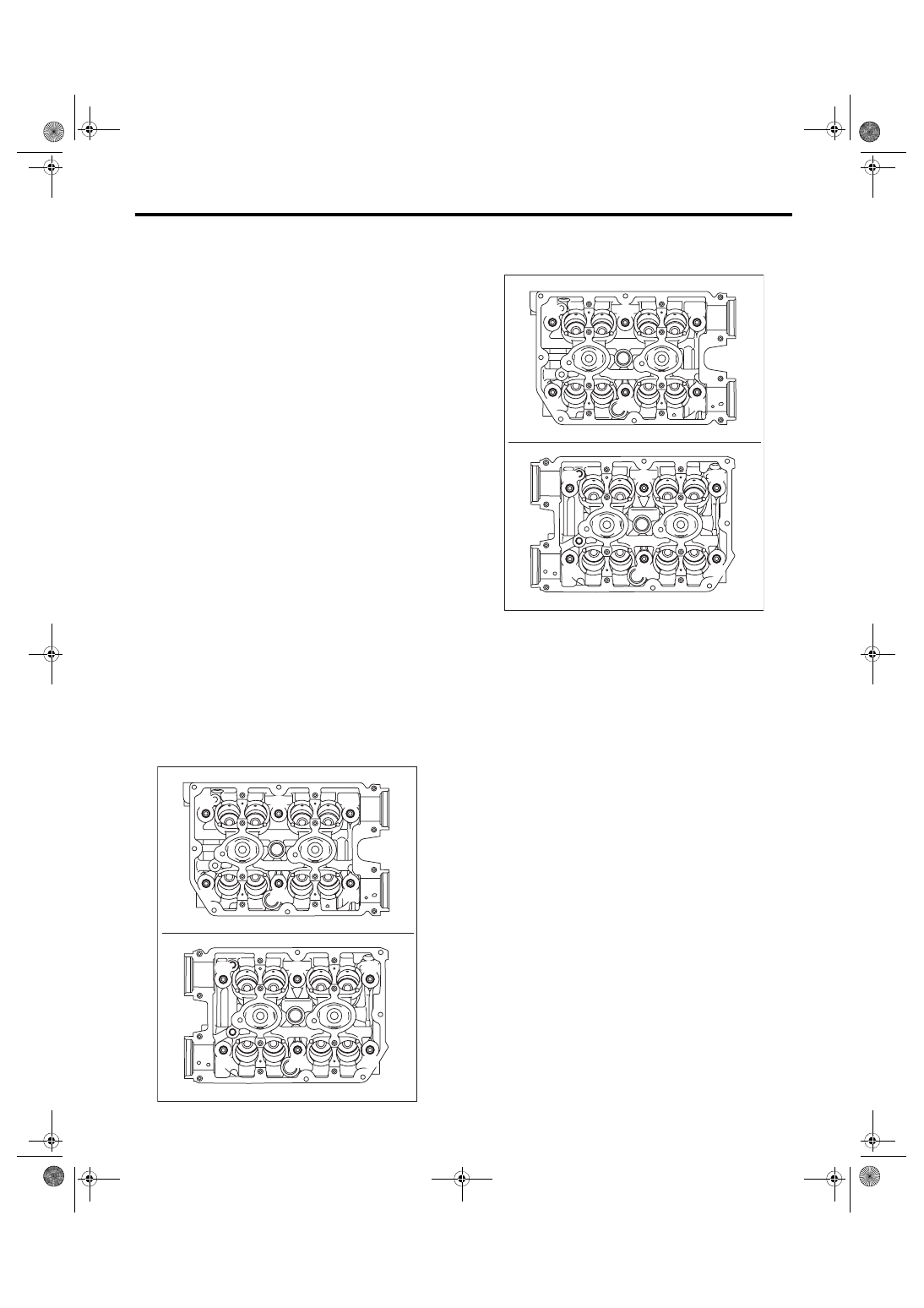
13) Remove the cylinder head bolts in alphabetical
order shown in the figure.
NOTE:
Leave the bolts (A) and (D) engaged by three or
four threads to prevent the cylinder head from fall-
ing.
14) While tapping the cylinder head with a plastic
hammer, separate it from cylinder block. Remove
the bolts (A) and (D) to remove cylinder head.
15) Remove the cylinder head gasket.
CAUTION:
Be careful not to scratch the mating surface of
cylinder head and cylinder block.
B: INSTALLATION
1) Install the cylinder head to the cylinder block.
CAUTION:
Be careful not to scratch the mating surface of
cylinder head and cylinder block.
NOTE:
Use a new cylinder head gasket.
(1) Clean the bolt threads and the bolt holes in
the cylinder block
CAUTION:
To avoid erroneous tightening of the bolts,
clean out the bolt holes sufficiently by blowing
with compressed air to eliminate engine cool-
ant etc.
(2) Apply a sufficient coat of engine oil to the
washer and bolt thread.
(3) Tighten all bolts to 40 N·m (4.1 kgf-m, 29.5
ft-lb) in alphabetical order.
ME-05983
(F)
(D)
(C)
(E)
(B)
(D)
(F)
(A)
(B)
(E)
(C)
(A)
ME-05983
(F)
(D)
(C)
(E)
(B)
(D)
(F)
(A)
(B)
(E)
(C)
(A)
Нет комментариевНе стесняйтесь поделиться с нами вашим ценным мнением.
Текст