Subaru Impreza 3 / Impreza WRX / Impreza WRX STI. Service manual — part 170
ME(w/o STI)-61
Camshaft
MECHANICAL
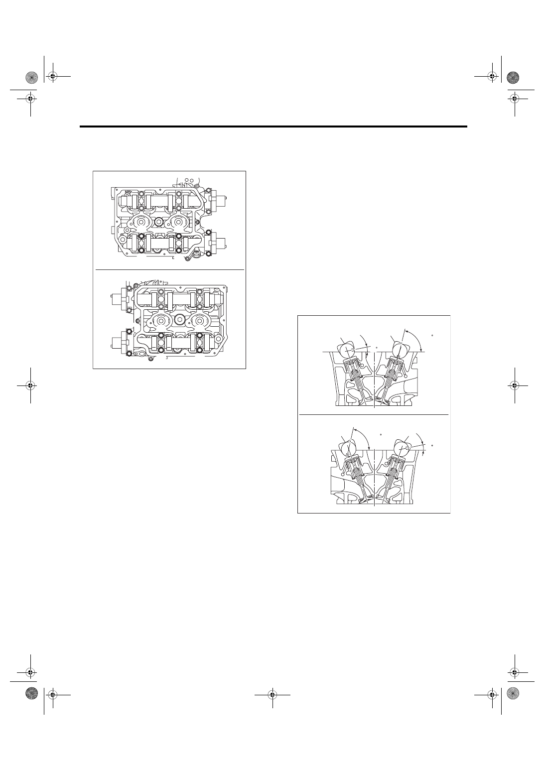
17) Loosen the lower side of the front camshaft cap
and the exhaust camshaft cap bolts equally, a little
at a time in alphabetical sequence shown in the fig-
ure.
18) Remove the front camshaft cap.
19) Remove the intake camshaft caps and intake
camshaft.
20) Remove the exhaust camshaft caps and ex-
haust camshaft.
NOTE:
Arrange camshaft caps in order so that they can be
installed in their original positions.
21) Remove the oil seal.
CAUTION:
Do not scratch the journal surface when remov-
ing the oil seal.
B: INSTALLATION
1) Install the camshaft.
Apply engine oil to the cylinder head at camshaft
bearing installation location before installing the
camshaft. Install the camshaft so that each valve is
close to or in contact with base circle of the cam
lobe.
NOTE:
• Set the camshaft to the position shown in the fig-
ure.
• When set at the position shown in the figure, it is
not necessary to rotate the camshaft RH when in-
stalling the timing belt, but it is necessary to rotate
the camshaft LH slightly.
Intake camshaft LH:
Rotate 80° clockwise.
Exhaust camshaft LH:
Rotate 45° counterclockwise.
ME-05979
(A)
(B)
(E)
(F)
(D)
(C)
(A)
(E)
(F)
(B)
(D)
(C)
(A) Cylinder head RH
(B) Cylinder head LH
(a) Intake camshaft
(b) Exhaust camshaft
ME-05038
(B)
(A)
(a)
(b)
11
77.5
(b)
(a)
77.5
11
ME(w/o STI)-62
Camshaft
MECHANICAL
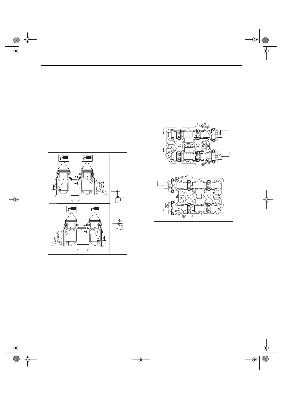
2) Install the camshaft cap.
(1) Apply small amount of liquid gasket to the
mating surface of cap.
NOTE:
• Install within 5 min. after applying liquid gasket.
• Do not apply liquid gasket excessively. Applying
excessively may cause excess gasket to come out
and flow toward oil seal, resulting in oil leak.
Liquid gasket:
THREE BOND 1217G (Part No. K0877Y0100)
or equivalent
Liquid gasket applying diameter:
Mating surfaces other than ranges A and B
2
±
0.5 mm (0.0787
±
0.0197 in)
Mating surfaces of ranges A and B
3
±
1 mm (0.1181
±
0.0394 in)
(2) Apply a thin coat of engine oil to the cap
journal surface, and install the camshaft cap to
the camshaft.
(3) Gradually tighten the camshaft cap in at
least two steps, in alphabetical order shown in
the figure, and then tighten to the specified
torque.
Tightening torque:
T1: 9.75 N·m (1.0 kgf-m, 7.2 ft-lb)
T2: 20 N·m (2.0 kgf-m, 14.8 ft-lb)
(4) After tightening the camshaft cap, ensure
the camshaft rotates only slightly while holding
it at base circle.
(A) Range A
(B) Range B
(C) Liquid gasket applying position of mating sur-
faces of ranges other than A and B
(D) Liquid gasket applying position of mating sur-
faces of ranges A and B
(E) 44.8 mm (1.7638 in)
(F) 65 mm (2.5591 in)
(G) φ2±0.5 mm (0.0787±0.0197 in)
(H) 0.5±0.5 mm (0.0197±0.0197 in)
(I) φ3±1 mm (0.1181±0.0394 in)
(J) 1 mm (0.0394 in) or less
ME-05769
(J)
(I)
(B)
(F)
A
A
B
B
B
(A)
(E)
A
A
B
B-B
(D)
A-A
(C)
(G)
(H)
ME-05980
(G)
(E)
(C)
(A)
(K)
(L)
(J)
(I)
(B)
(D)
(H)
(F)
(G)
(E)
(C)
(A)
(K)
(L)
(J)
(I)
(B)
(D)
(H)
(F)
T1
T2
T1
T2
T2
T2
T1
T1
ME(w/o STI)-63
Camshaft
MECHANICAL
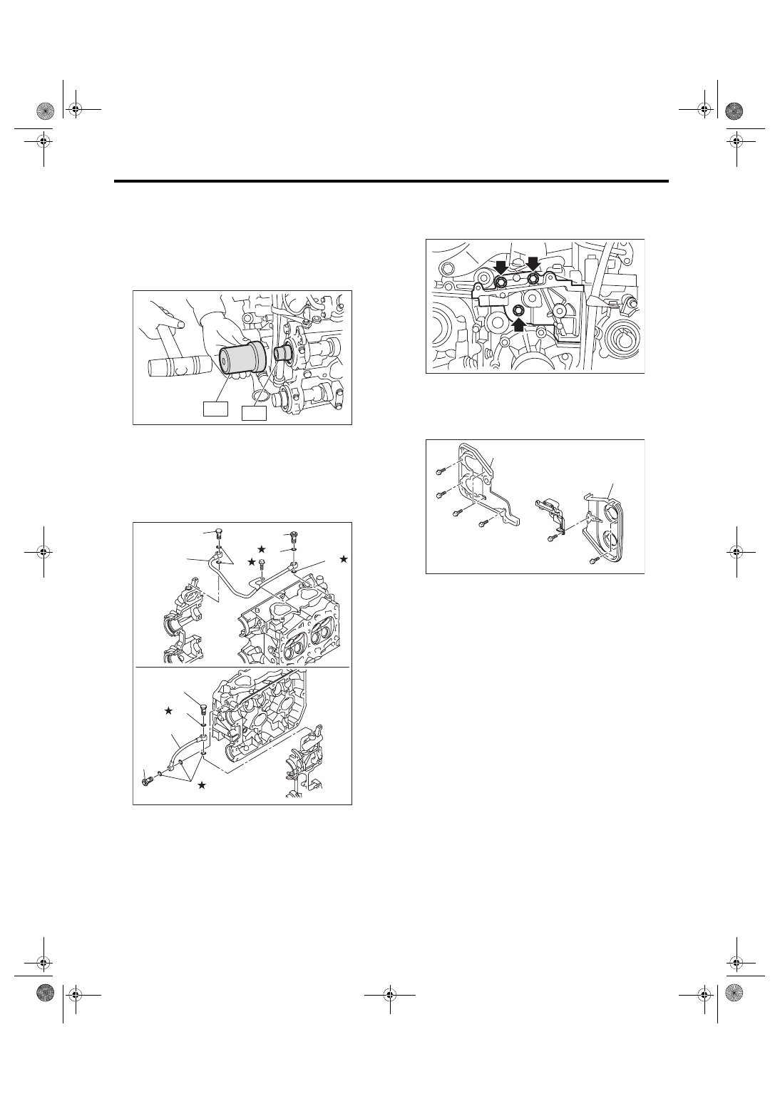
3) Apply a thin coat of engine oil to the periphery of
the camshaft oil seal and oil seal lip, and install the
oil seal on the camshaft using ST1 and ST2.
NOTE:
Use a new oil seal.
ST1 499587600
OIL SEAL INSTALLER
ST2 499597200
OIL SEAL GUIDE
4) Install the oil pipe to the front camshaft cap using
the union bolt without filter (without protrusion).
NOTE:
Use a new gasket.
Tightening torque:
29 N·m (3.0 kgf-m, 21.4 ft-lb)
5) Install the tensioner bracket.
Tightening torque:
24.5 N·m (2.5 kgf-m, 18.1 ft-lb)
6) Install the timing belt cover No. 2 RH (A) and tim-
ing belt cover No. 2 LH (B).
Tightening torque:
5 N·m (0.5 kgf-m, 3.7 ft-lb)
7) Install the cam sprocket. <Ref. to ME(w/o STI)-
57, INSTALLATION, Cam Sprocket.>
8) Install the timing belt. <Ref. to ME(w/o STI)-50,
9) Adjust the valve clearance. <Ref. to ME(w/o
STI)-28, ADJUSTMENT, Valve Clearance.>
(A) Union bolt with filter (with protrusion)
(B) Union bolt without filter (without protrusion)
(C) Oil pipe RH
(D) Oil pipe LH
(E) Gasket
ME-05002
ST1
ST2
ME-05033
(A)
(B)
(D)
(A)
(B)
(C)
(E)
(E)
(E)
(E)
(E)
ME-04984
ME-04836
(B)
(A)
ME(w/o STI)-64
Camshaft
MECHANICAL
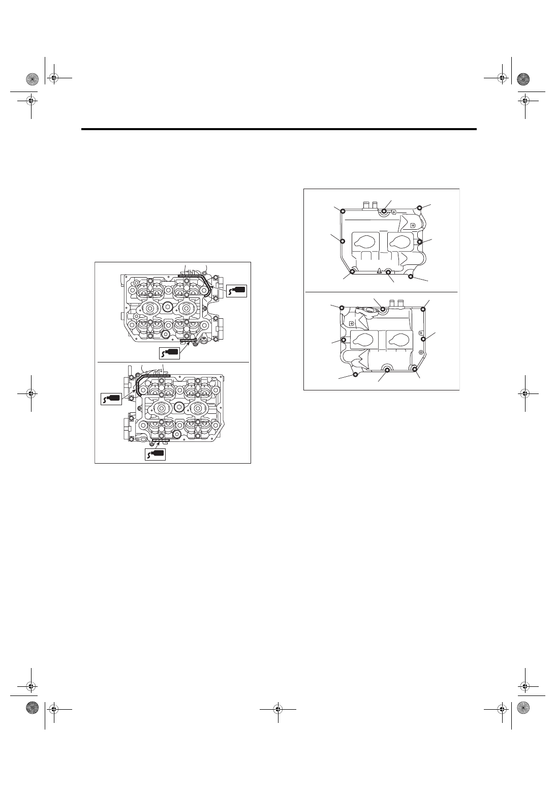
10) Install the rocker cover.
(1) Install the rocker cover gasket to the rocker
cover. (outer section and ignition coil section)
NOTE:
Use a new rocker cover gasket.
(2) Apply liquid gasket to the specified point of
the cylinder head.
NOTE:
Install within 5 min. after applying liquid gasket.
Liquid gasket:
THREE BOND 1217G (Part No. K0877Y0100)
or equivalent
(3) Install the rocker cover onto cylinder heads.
Ensure the gasket is properly positioned during
installation.
(4) Temporarily tighten the rocker cover bolts in
alphabetical order shown in the figure, and then
tighten to specified torque in alphabetical order.
Tightening torque:
6.4 N·m (0.7 kgf-m, 4.7 ft-lb)
ME-05981
ME-05982
(E)
(F)
(H)
(G)
(D),(L)
(A),(I)
(C),(K)
(B),(J)
(B),(J)
(H)
(F)
(C),(K)
(E)
(A),(I)
(D),(L)
(G)
Нет комментариевНе стесняйтесь поделиться с нами вашим ценным мнением.
Текст