Subaru Impreza 3 / Impreza WRX / Impreza WRX STI. Service manual — part 172
ME(w/o STI)-69
Cylinder Head
MECHANICAL
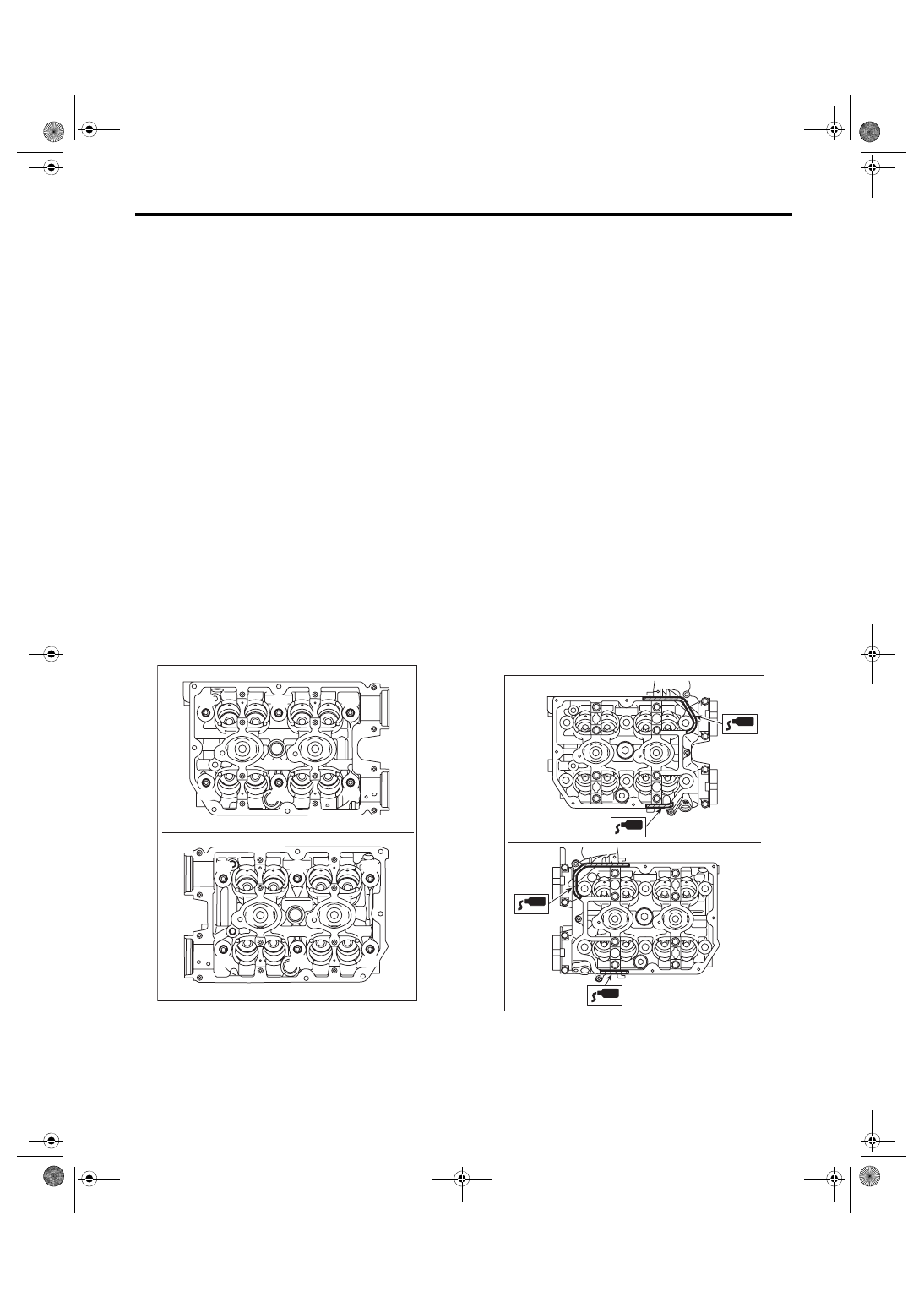
(4) Retighten all bolts to 95 N·m (9.7 kgf-m,
70.1 ft-lb) in alphabetical order.
CAUTION:
If the bolt makes stick-slip sound during tight-
ening, repeat the procedure from step (1). In
this case, the cylinder head gasket can be re-
used.
(5) Loosen all the bolts by 180° in the reverse
order of installing, and loosen them further by
180°.
(6) Tighten all bolts to 10 N·m (1.0 kgf-m, 7.4 ft-lb)
in alphabetical order.
(7) Retighten all bolts to 30 N·m (3.1 kgf-m,
22.1 ft-lb) in alphabetical order.
(8) Retighten all bolts to 70 N·m (7.1 kgf-m,
51.6 ft-lb) in alphabetical order.
(9) Retighten all bolts by 80 — 90° in alphabet-
ical order.
(10) Retighten all bolts by 40 — 45° in alphabet-
ical order.
CAUTION:
The tightening angle of the bolt should not ex-
ceed 45°.
(11) Retighten bolts (A) and (B) by 40 — 45°.
CAUTION:
Make sure the total “tightening angle” of steps
(10) and (11) does not exceed 90°.
2) Install the oil level gauge guide. (LH side only)
Tightening torque:
6.4 N·m (0.7 kgf-m, 4.7 ft-lb)
3) Install the camshaft. <Ref. to ME(w/o STI)-61,
4) Install the oil pipe. <Ref. to LU(STI)-27, INSTAL-
5) Install the A/C compressor bracket on cylinder
head.
Tightening torque:
36 N·m (3.7 kgf-m, 26.6 ft-lb)
6) Install the secondary air combination valve.
<Ref. to EC(w/o STI)-31, INSTALLATION, Second-
7) Install the cam sprocket. <Ref. to ME(w/o STI)-
57, INSTALLATION, Cam Sprocket.>
8) Install the timing belt. <Ref. to ME(w/o STI)-50,
9) Adjust the valve clearance. <Ref. to ME(w/o
STI)-28, ADJUSTMENT, Valve Clearance.>
10) Install the rocker cover.
(1) Install the rocker cover gasket to the rocker
cover. (outer section and ignition coil section)
NOTE:
Use a new rocker cover gasket.
(2) Apply liquid gasket to the specified point of
the cylinder head.
NOTE:
Install within 5 min. after applying liquid gasket.
Liquid gasket:
THREE BOND 1217G (Part No. K0877Y0100)
or equivalent
(3) Install the rocker cover onto cylinder heads.
Ensure the gasket is properly positioned during
installation.
ME-05984
(F)
(A)
(C)
(D)
(B)
(E)
(C)
(A)
(F)
(E)
(B)
(D)
ME-05981
ME(w/o STI)-70
Cylinder Head
MECHANICAL
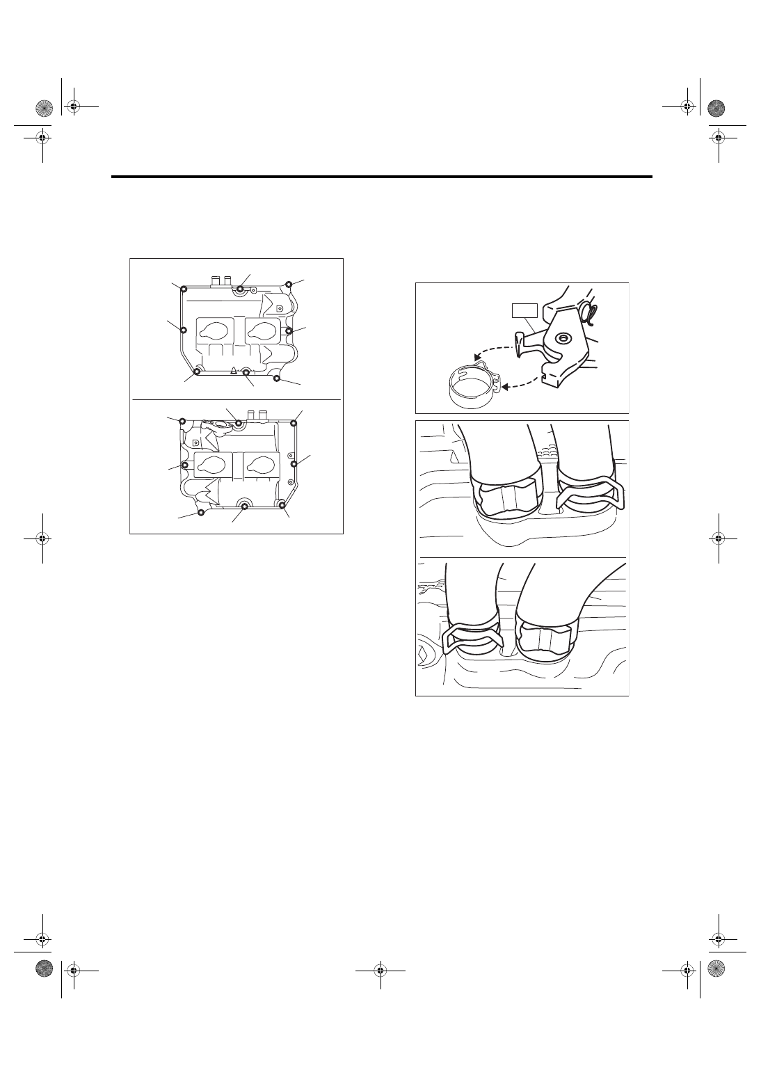
(4) Temporarily tighten the rocker cover bolts in
alphabetical order shown in the figure, and then
tighten to specified torque in alphabetical order.
Tightening torque:
6.4 N·m (0.7 kgf-m, 4.7 ft-lb)
11) Connect the PCV hose (A) and PCV hose as-
sembly (B) to the rocker cover.
NOTE:
Use a new clamp for the PCV hose (A), fit the cut
out in the ST with the protrusion on the clamp as
shown in the figure, and lock the clamp.
ST 18353AA000 CLAMP PLIERS
12) Install the timing belt cover. <Ref. to ME(w/o
STI)-47, INSTALLATION, Timing Belt Cover.>
13) Install the crank pulley. <Ref. to ME(w/o STI)-
45, INSTALLATION, Crank Pulley.>
14) Install the intake manifold. <Ref. to FU(w/o
STI)-22, INSTALLATION, Intake Manifold.>
15) Install the rear side belt. <Ref. to ME(w/o STI)-
39, REAR SIDE BELT, INSTALLATION, V-belt.>
16) Install the engine to the vehicle. <Ref. to ME(w/
o STI)-33, INSTALLATION, Engine Assembly.>
ME-05982
(E)
(F)
(H)
(G)
(D),(L)
(A),(I)
(C),(K)
(B),(J)
(B),(J)
(H)
(F)
(C),(K)
(E)
(A),(I)
(D),(L)
(G)
ME-04374
ST
ME-05768
(A)
(B)
(A)
(B)
ME(w/o STI)-71
Cylinder Head
MECHANICAL
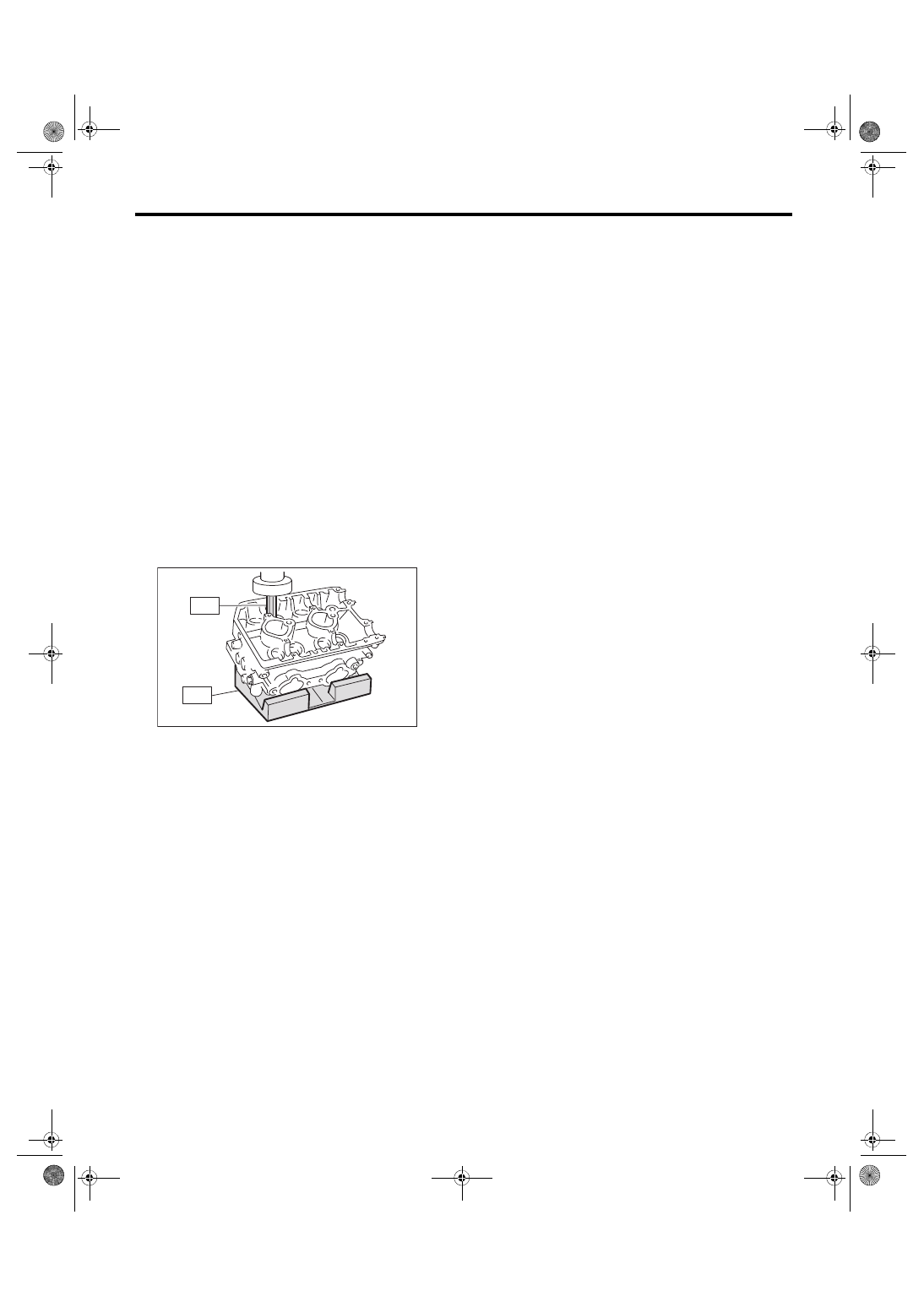
C: DISASSEMBLY
1) Remove the valve lifter.
2) Place the cylinder head on ST1.
ST1 498267600
CYLINDER HEAD TABLE
3) Using ST2, compress the valve spring and re-
move the valve spring retainer key. Remove each
valve and valve spring.
ST2 499718000
VALVE SPRING REMOVER
NOTE:
• Mark each valve to prevent confusion.
• Pay careful attention not to damage the lips of in-
take valve oil seals and exhaust valve oil seals.
• Keep all the removed parts in order for re-install-
ing in their original positions.
• For removal and installation procedures of the
valve guide, intake valve oil seal and exhaust valve
oil seal, refer to “INSPECTION”. <Ref. to ME(w/o
STI)-73, VALVE GUIDE, INSPECTION, Cylinder
Head.> <Ref. to ME(w/o STI)-76, INTAKE AND
EXHAUST VALVE OIL SEAL, INSPECTION, Cyl-
ME-05003
ST1
ST2
ME(w/o STI)-72
Cylinder Head
MECHANICAL
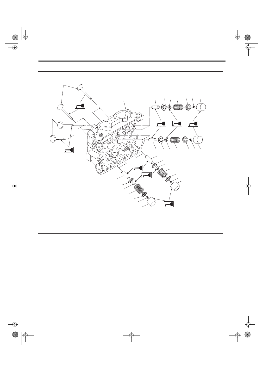
D: ASSEMBLY
1) Install the valve spring and valve.
(1) Coat the valve stem of each valve with en-
gine oil and insert the valve into valve guide.
NOTE:
When inserting the valve into valve guide, use spe-
cial care not to damage the oil seal lip.
(2) Set the cylinder head on ST1.
ST1 498267600
CYLINDER HEAD TABLE
(3) Install the valve spring and valve spring re-
tainer.
NOTE:
Be sure to install the valve spring with its close-
coiled end facing the cylinder head side.
(1)
Exhaust valve
(5)
Intake valve oil seal
(9)
Valve lifter
(2)
Intake valve
(6)
Valve spring
(10) Exhaust valve oil seal
(3)
Cylinder head
(7)
Valve spring retainer
(11) Intake valve guide
(4)
Valve spring seat
(8)
Valve spring retainer key
(12) Exhaust valve guide
(3)
(1)
(12)
(10)
(4)
(6)
(7)
(8)
(9)
(10)
(4)
(6)
(7)
(8)
(9)
ME-04990
(12)
(2)
(11)
(4) (5)
(6)
(7) (8)
(9)
(11)
(4) (5)
(6)
(7) (8) (9)
Нет комментариевНе стесняйтесь поделиться с нами вашим ценным мнением.
Текст