Subaru Impreza 3 / Impreza WRX / Impreza WRX STI. Service manual — part 116
SC(STI)-20
Starter
STARTING/CHARGING SYSTEMS
7. PERFORMANCE TEST
The starter should be submitted to performance
tests whenever it has been overhauled, to assure
its satisfactory performance when installed on the
engine.
Three performance tests, no-load test, load test,
and lock test, are presented here; however, if the
load test and lock test cannot be performed, carry
out at least the no-load test.
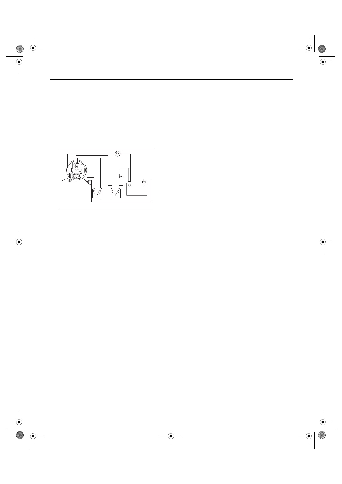
For these performance tests, use the circuit shown
in figure.
1) Adjust the variable resistance with the switch on
until the voltage is 11 V, and read the value dis-
played by the ammeter to measure starter speed.
Compare these values with the standard.
No-load test (standard):
Voltage/Current
6MT
Max. 11 V/90 A or less
5MT
Max. 11 V/95 A or less
Rotating speed
6MT
2,860 rpm or more
5MT
2,500 rpm or more
2) Apply the specified braking torque to starter. The
condition is normal if the current draw and starter
speed are within standard.
Load test (standard):
Voltage/Load
6MT
8 V/9.3 N·m (0.9 kgf-m, 6.9 ft-lb) or more
5MT
7.5 V/8.84 N·m (0.9 kgf-m, 6.5 ft-lb) or more
Current/Speed
6MT
280 A/860 rpm or more
5MT
300 A/870 rpm or more
3) With the starter stalled, or not rotating, measure
the torque developed and current draw when the
voltage is adjusted to standard voltage.
Lock test (standard):
Voltage/Current
6MT
4 V/515 A or less
5MT
4 V/680 A or less
Torque
6MT
16 N·m (1.6 kgf-m, 11.8 ft-lb) or more
5MT
17 N·m (1.7 kgf-m, 12.5 ft-lb) or more
8. OTHER INSPECTIONS
Check that the starter does not have deformation,
cracks and any other damage.
(A) Variable resistance
(B) Magnet switch
(C) Starter body
(A)
(B)
(C)
12V
+
A
V
B
S
M
SC-00077
SC(STI)-21
Generator
STARTING/CHARGING SYSTEMS
3. Generator
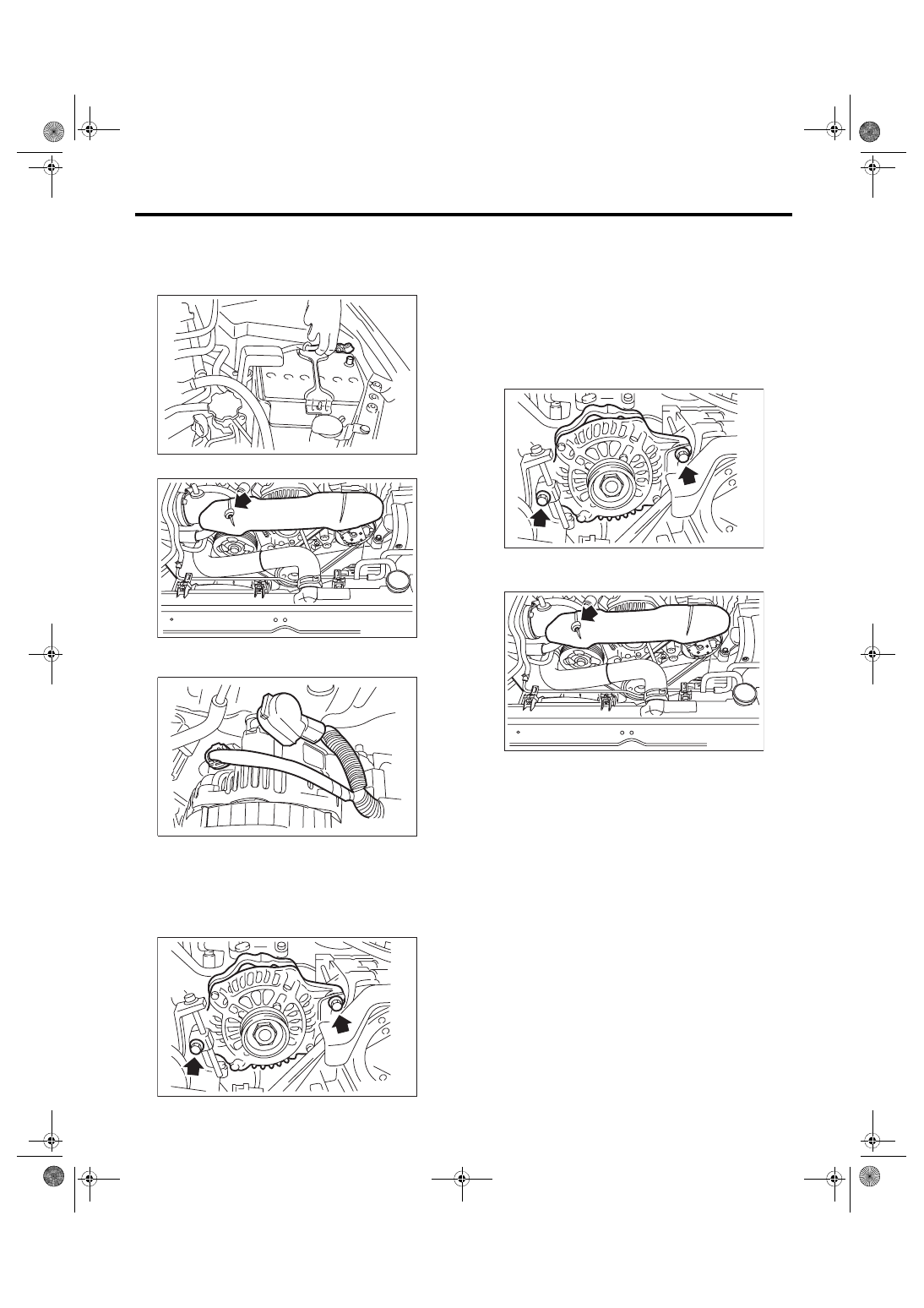
A: REMOVAL
1) Disconnect the ground cable from battery.
2) Remove the V-belt covers.
3) Disconnect the connector and terminal from
generator.
4) Remove the front side belts. <Ref. to ME(STI)-
40, FRONT SIDE BELT, REMOVAL, V-belt.> <Ref.
to ME(w/o STI)-38, FRONT SIDE BELT, REMOV-
5) Remove the bolts which install the generator
onto bracket.
B: INSTALLATION
Install in the reverse order of removal.
CAUTION:
Check and adjust the front side belt tension.
<Ref. to ME(STI)-46, FRONT SIDE BELT, IN-
SPECTION, V-belt.> <Ref. to ME(w/o STI)-44,
FRONT SIDE BELT, INSPECTION, V-belt.>
Tightening torque:
25 N·m (2.5 kgf-m, 18.4 ft-lb)
Tightening torque:
13 N·m (1.3 kgf-m, 9.6 ft-lb)
IN-00203
FU-03487
SC-02154
SC-00179
SC-00179
FU-03487
SC(STI)-22
Generator
STARTING/CHARGING SYSTEMS
C: DISASSEMBLY
1) Remove the four through-bolts.
2) Use a drier to heat the rear cover (A) portion to
50°C (122°F).
3) Insert the end of a flat tip screwdriver into the
gap between stator core and front cover. Pry them
apart to disassemble.
4) Using a vise, support the rotor and remove the
pulley nut, and remove the rotor from the front cov-
er.
CAUTION:
When holding the rotor with a vise, place alumi-
num plates or wooden pieces on the vise jaws
to prevent rotor from damage.
5) Use the following procedures to remove the ball
bearings.
(1) Remove the bolt, and then detach the bear-
ing retainer.
(A) Screwdriver
SC-00078
SC-00079
(A)
SC-00080
(A)
(A)
(A) Front cover
(B) Pulley
(C) Pulley nut
(D) Rotor
SC-00035
(A)
(B)
(C)
(D)
SC-00036
SC-00081
SC(STI)-23
Generator
STARTING/CHARGING SYSTEMS
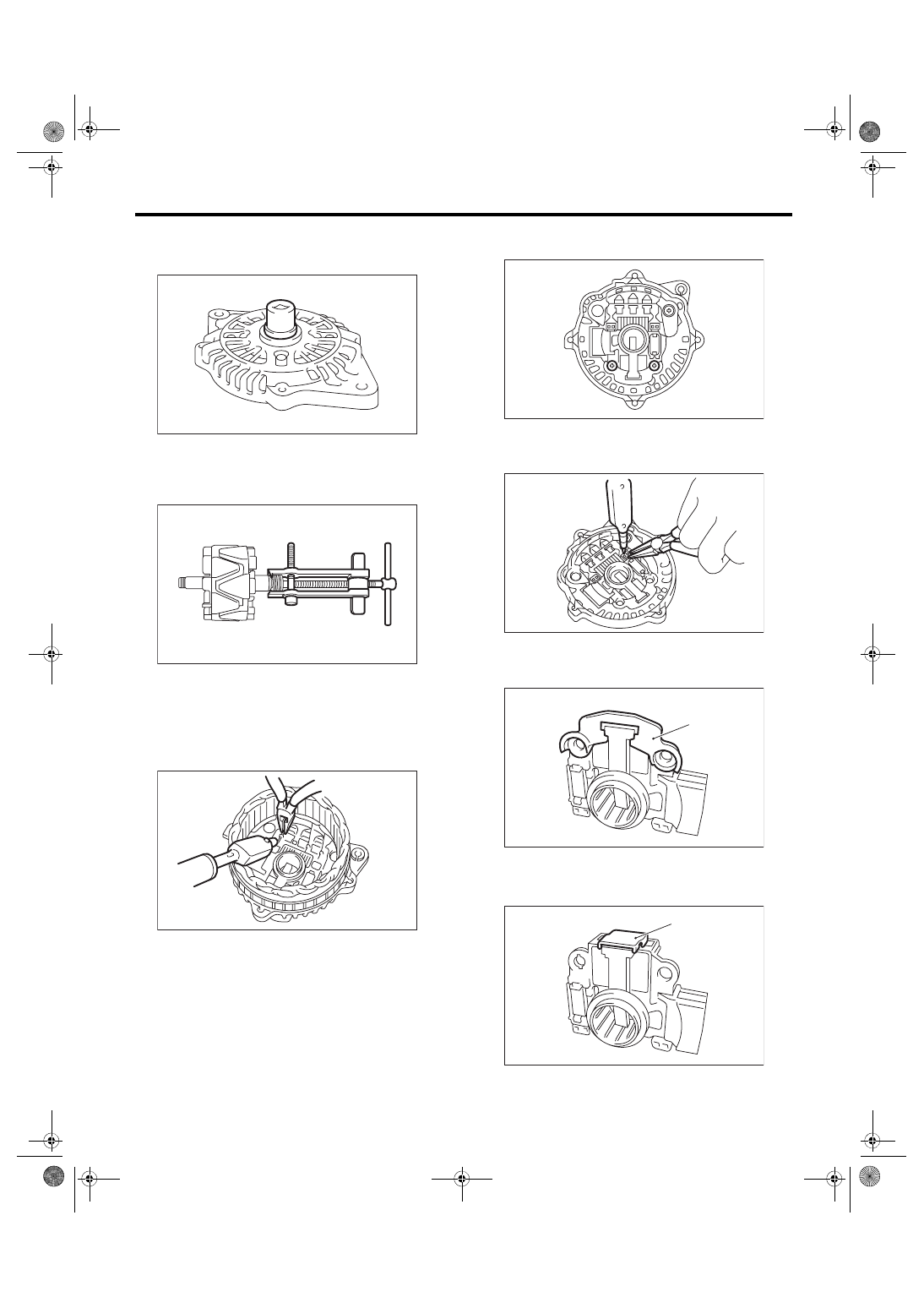
(2) Firmly attach an appropriate tool (such as a
correct size socket wrench) to the bearing inner
race.
(3) Use the press to push the ball bearings out
from the front cover.
6) Using the bearing puller, remove the bearings
from the rotor.
7) Disconnect the connection between the rectifier
and stator coil, then remove the stator coil.
CAUTION:
The rectifier is easily damaged by heat. Do not
allow a 180 — 270 W soldering iron to contact
the terminals for 5 seconds or more at a time.
8) Use the following procedures to remove the IC
regulator.
(1) Remove the screws which secure the IC
regulator to the rear cover.
(2) Disconnect the connection between the IC
regulator and rectifier, then remove the IC reg-
ulator.
9) Use the following procedures to remove the
brush.
(1) Remove the cover A.
(2) Remove the cover B.
SC-00082
SC-00046
SC-00083
(A) Cover A
(A) Cover B
SC-00084
SC-00085
SC-00086
(A)
SC-00087
(A)
Нет комментариевНе стесняйтесь поделиться с нами вашим ценным мнением.
Текст