Subaru Impreza 3 / Impreza WRX / Impreza WRX STI. Service manual — part 114
SC(STI)-12
Starter
STARTING/CHARGING SYSTEMS
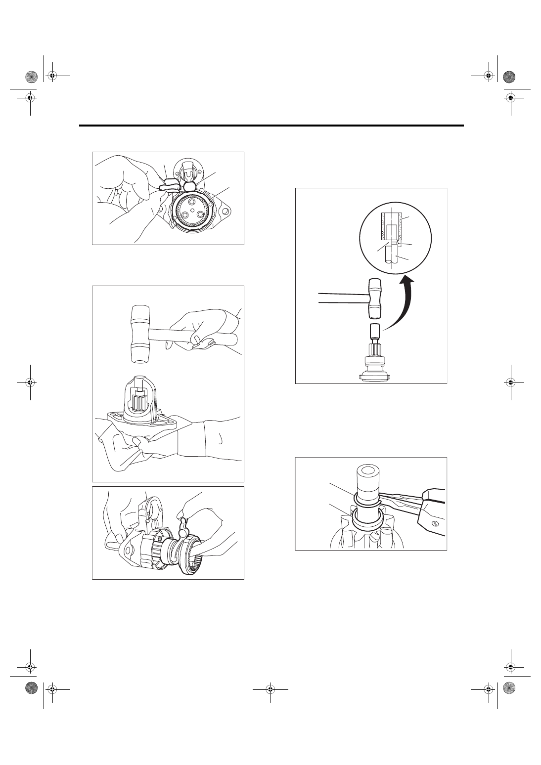
8) Remove seal rubber (A), plate (B), and seal rub-
ber (C).
9) Lightly tap the starter housing assembly with a
plastic hammer as shown in the figure, and remove
the overrunning clutch, internal gear assembly,
shaft and shift lever together as one unit.
10) Use the following procedures to remove the
overrunning clutch from the shaft.
(1) Use an appropriate tool (such as a fit socket
wrench), and remove the stopper from snap
ring by lightly tapping the stopper with a plastic
hammer.
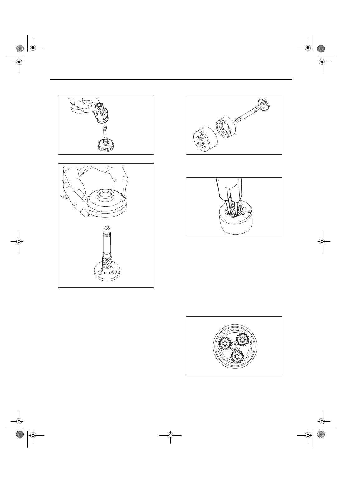
(2) Remove snap ring (A) from the shaft, and
remove stopper (B).
(A)
SC-02230
(B)
(C)
SC-02231
SC-02235
(A) Appropriate tool
(B) Snap ring
(C) Shaft
(D) Stopper
(A)
(B)
(C)
(D)
SC-02232
SC-02134
(A)
(B)
SC(STI)-13
Starter
STARTING/CHARGING SYSTEMS
(3) Remove the overrunning clutch from the
shaft.
11) Separate the internal gear assembly and shaft.
D: ASSEMBLY
1. STI MODEL
1) Use the following procedures to install the shaft.
(1) Apply grease to the shaft sliding surfaces of
the internal gear assembly.
Grease:
DENSO HL50
(2) Assemble the shaft to the internal gear as-
sembly.
(3) Install the snap ring to shaft.
NOTE:
Use new snap rings.
(4) Apply grease to the pinion gear attachment
area.
Grease:
DENSO HL50
(5) Attach the pinion gear to the pin.
(6) Apply grease to the pinion gear, internal
gear assembly, and on top of the shaft pin.
NOTE:
• Apply grease so that it contacts each gear.
• Be careful not to allow dirt to get in.
Grease:
DENSO HL50
(7) Install the starter plate.
SC-02233
SC-02234
SC-02219
SC-02218
SC-02215
SC(STI)-14
Starter
STARTING/CHARGING SYSTEMS
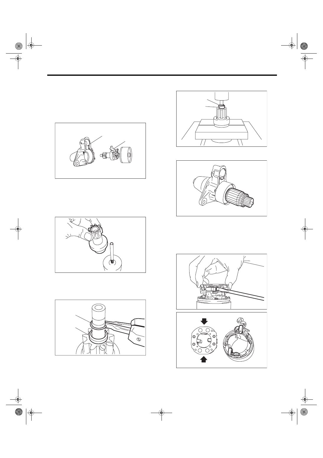
2) Assemble the overrunning clutch and shift lever
(B) to the starter housing (A) as a unit.
NOTE:
Apply grease to the contact portion of the shift le-
ver.
Grease:
DENSO HL50
3) Assemble the overrunning clutch as follows:
(1) Apply grease to the spline portion of the
shaft.
Grease:
DENSO HL50
(2) Install the overrunning clutch to shaft.
(3) Pass stopper (B) through the shaft, and at-
tach snap ring (A).
NOTE:
Use new snap rings.
(4) Using a press, pressure fit stopper (B) into
snap ring (A).
4) Install the armature to the internal gear assem-
bly.
5) Attach the two brushes wired to the yoke assem-
bly to the brush holder assembly.
NOTE:
As shown in the figure, use a flat tip screwdriver,
etc. to hold the brush spring and insert the brush
while being careful not to damage the brush.
(A)
(B)
SC-02214
SC-02217
SC-02134
(A)
(B)
SC-00068
(A)
(B)
SC-02213
SC-02220
SC-02212
SC(STI)-15
Starter
STARTING/CHARGING SYSTEMS
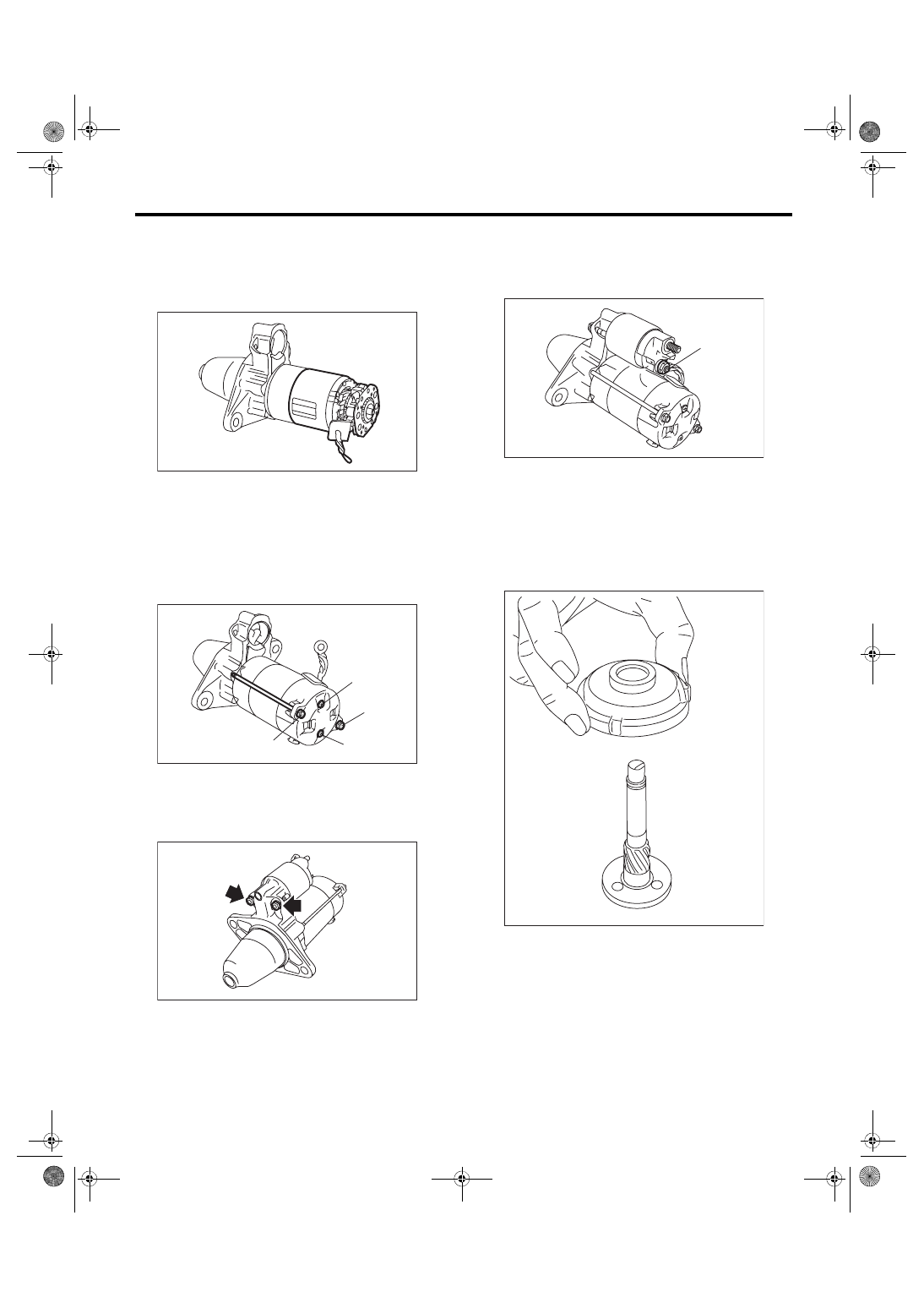
6) Install the yoke assembly and brush holder as-
sembly as a single unit to the armature.
NOTE:
Spread the brush with your fingers, being careful
not to damage the brush.
7) Install starter cover assembly to the brush holder
assembly with screws (B).
Tightening torque:
1.4 N·m (0.1 kgf-m, 1.0 ft-lb)
8) Tighten the through bolts (A) on both sides.
Tightening torque:
6 N·m (0.6 kgf-m, 4.4 ft-lb)
9) Attach the magnet switch assembly to the starter
housing assembly.
Tightening torque:
7.5 N·m (0.8 kgf-m, 5.5 ft-lb)
10) Connect terminal M (A) to magnet switch as-
sembly.
Tightening torque:
10 N·m (1.0 kgf-m, 7.4 ft-lb)
2. EXCEPT FOR STI MODEL
1) Apply grease to the shaft sliding surfaces of the
internal gear assembly.
Grease:
Multemp #6129 or equivalent
2) Assemble the shaft to the internal gear assem-
bly.
SC-02211
SC-02210
(A)
(B)
(A)
(B)
SC-02209
SC-02208
(A)
SC-02234
Нет комментариевНе стесняйтесь поделиться с нами вашим ценным мнением.
Текст