Subaru Impreza 3 / Impreza WRX / Impreza WRX STI. Service manual — part 115
SC(STI)-16
Starter
STARTING/CHARGING SYSTEMS
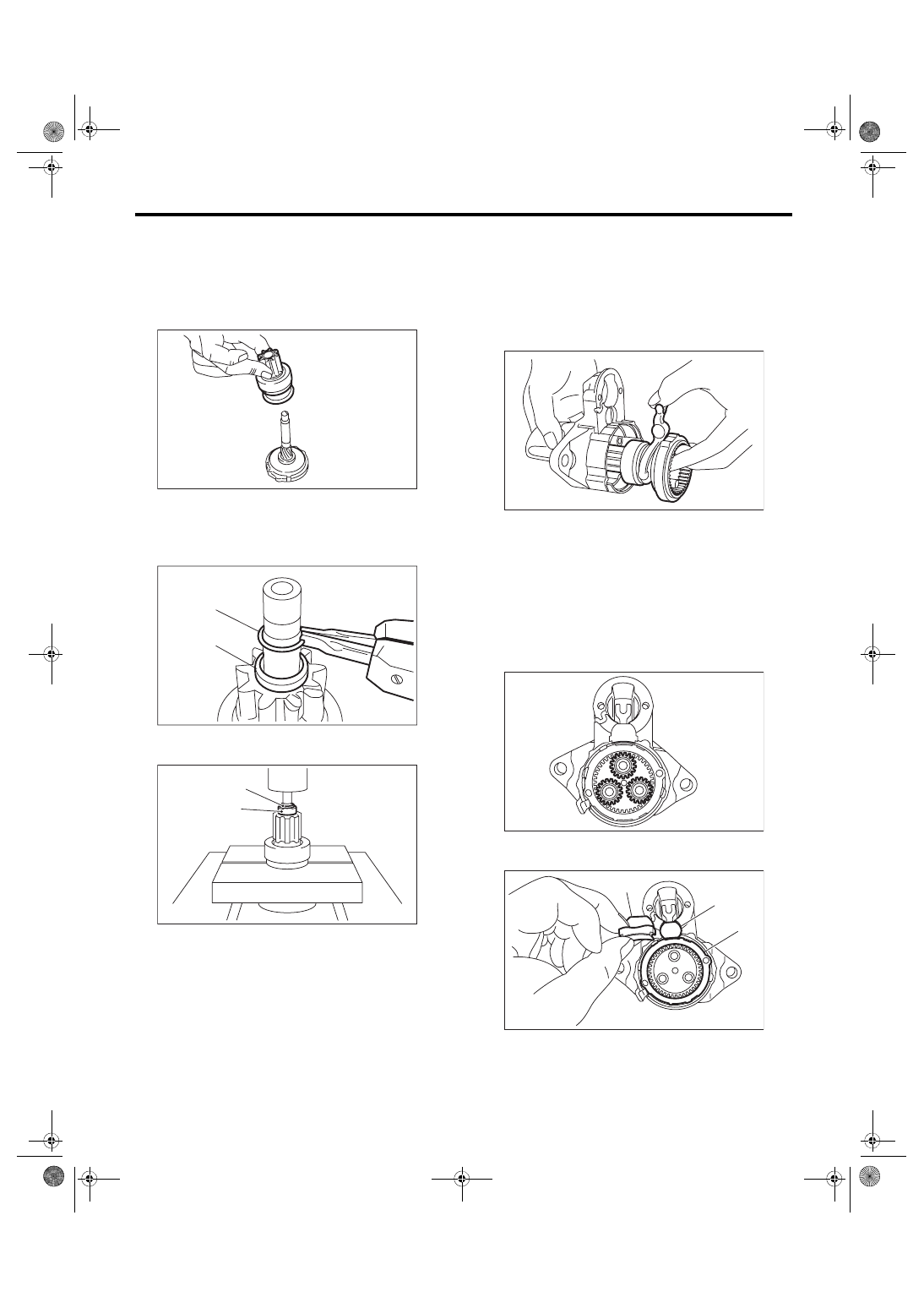
3) Assemble the overrunning clutch as follows:
(1) Apply grease to the spline portion of the
shaft.
Grease:
Multemp #6129 or equivalent
(2) Install the overrunning clutch to shaft.
(3) Pass stopper (B) through the shaft assem-
bly, and attach snap ring (A).
NOTE:
Use new stoppers and snap rings.
(4) Using a press, pressure fit stopper (B) into
snap ring (A).
4) Assemble the overrunning clutch, internal gear
assembly, shaft and shift lever as a single unit into
the starter housing assembly.
NOTE:
Apply grease to the moving parts of the shift lever.
Grease:
Multemp #6129 or equivalent
5) Apply grease to the inside of the internal gear
assembly and pinion gear, and attach the pinion
gear to the internal gear assembly.
NOTE:
• Apply grease evenly to the contact surfaces of
each gear.
• Be careful that no debris becomes attached.
Grease:
Molykote
®
AG650 or equivalent
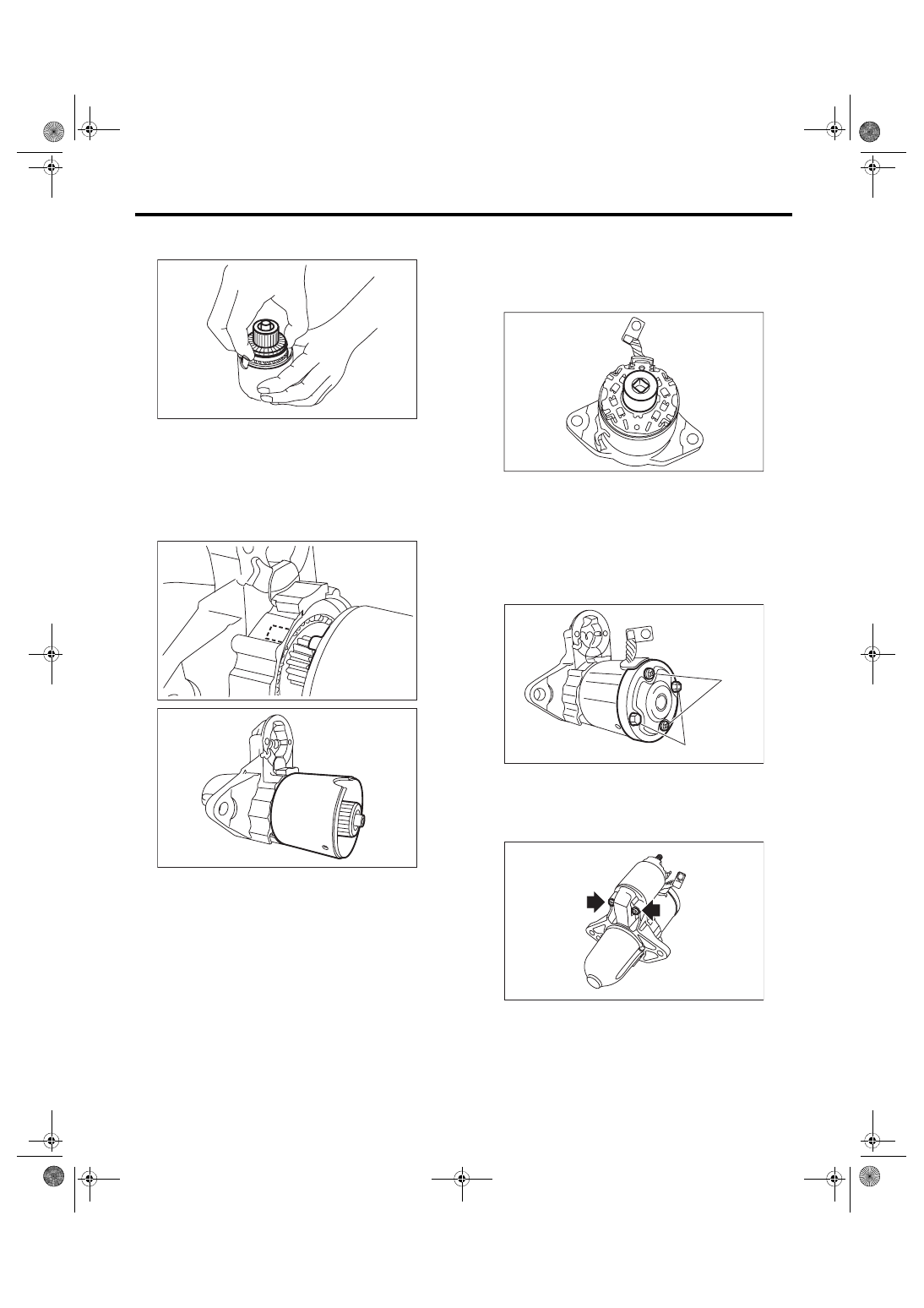
6) Install seal rubber (A), plate (B), and seal rubber
(C).
SC-02233
SC-02134
(A)
(B)
SC-00068
(A)
(B)
SC-02235
SC-02229
(A)
SC-02230
(B)
(C)
SC(STI)-17
Starter
STARTING/CHARGING SYSTEMS
7) Assemble the armature assembly to the yoke
assembly.
8) Attach the armature assembly and yoke assem-
bly to the starter housing assembly together as a
single unit.
NOTE:
As shown in the figure, match the protrusion of the
yoke assembly to the cut out of the starter housing
assembly.
9) Use an appropriate tool (such as correctly sized
socket wrenches) and attach the brush holder as-
sembly to the armature assembly.
NOTE:
Be careful not to damage the brushes.
10) Secure starter cover assembly to the brush
holder assembly with screws (A).
Tightening torque:
1.4 N·m (0.1 kgf-m, 1.0 ft-lb)
11) Install through bolts (B) on both sides.
Tightening torque:
6 N·m (0.6 kgf-m, 4.4 ft-lb)
12) Attach the magnet switch assembly to the start-
er housing assembly.
Tightening torque:
7.5 N·m (0.8 kgf-m, 5.5 ft-lb)
SC-02228
SC-02236
SC-02227
SC-02237
SC-02225
(A)
(B)
SC-02224
SC(STI)-18
Starter
STARTING/CHARGING SYSTEMS
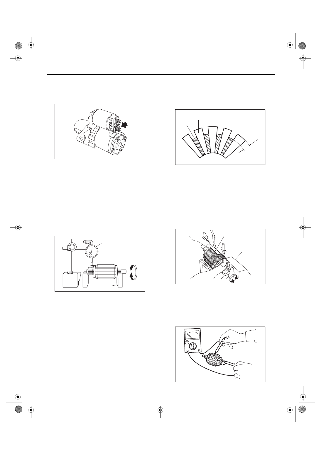
13) Attach the cable to the terminal M of the mag-
net switch assembly, and secure with nuts.
Tightening torque:
10 N·m (1.0 kgf-m, 7.4 ft-lb)
E: INSPECTION
1. ARMATURE
1) Check the commutator for signs of seizure or
stepped wear caused by roughness of the surface.
If there is light wear, use sandpaper to repair.
2) Check for runout on the commutator. If exces-
sive, replace the armature.
Commutator runout:
Standard
0.05 mm (0.0020 in)
Limit
0.10 mm (0.0039 in)
3) Check the depth of the segment mold. If it is not
within the standard, replace the armature.
Depth of segment mold:
Standard
0.5 mm (0.020 in)
4) Place the armature on the growler tester to
check for short circuits. While slowly turning the ar-
mature, support the steel sheet for the armature
core. If the circuit of the armature is shorted, the
steel sheet will vibrate, causing it to move towards
the core. When the steel sheet has moved or vi-
brated, replace the armature.
5) Use a circuit tester to touch the probe of one side
to the commutator segment, and the other probe to
the shaft. If there is continuity, replace the arma-
ture.
(A) Dial gauge
(B) V-block
SC-02223
SC-00021
(A)
(B)
(A) Depth of mold
(B) Segment
(C) Mold
(A) Steel sheet
(B) Growler tester
(C)
(B)
(A)
SC-00022
(A)
(B)
SC-00023
SC-00024
SC(STI)-19
Starter
STARTING/CHARGING SYSTEMS
2. YOKE
Make sure that the pole is set at the predetermined
position.
3. OVERRUNNING CLUTCH
Check that there is no wear or damage to the piston
teeth. Replace the overrunning clutch if it is dam-
aged.
Check that it rotates smoothly when rotated in the
correct direction (counterclockwise) and does not
return to the other direction. Replace the overrun-
ning clutch if any fault is found.
CAUTION:
To prevent spilling of grease, do not clean the
overrunning clutch with oil.
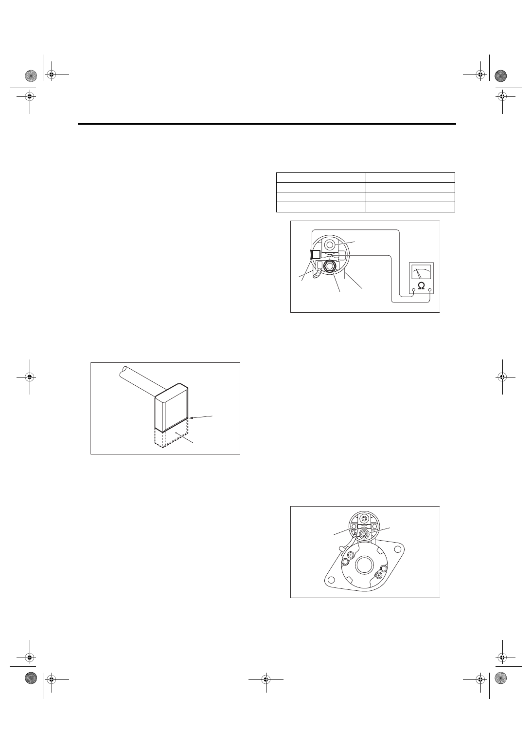
4. BRUSH AND BRUSH HOLDER
1) Measure the length of the brush. Replace if it ex-
ceeds service limits or there is abnormal wear or
cracks.
Brush length:
Standard
12.3 mm (0.484 in)
Limit
7.0 mm (0.276 in)
2) Check that the brush moves smoothly in the
brush holder.
3) Measure the brush spring force with a spring
scale. Replace the brush holder if below the service
limit.
Brush spring force:
Standard
15.9 — 19.5 N (1.62 — 1.99 kgf, 3.57 — 4.38
lbf) (When new)
Limit
2.5 N (0.25 kgf, 0.56 lbf)
5. SWITCH ASSEMBLY
Using a circuit tester (set to “ohm”), check that
there is continuity between terminals S and M, and
between terminal S and ground.
Also check to be sure there is no continuity be-
tween M terminal and B.
Resistance between switch assembly termi-
nals:
6. SWITCH ASSEMBLY OPERATION
1) Using a lead wire, connect the terminal S of
switch assembly to positive terminal of battery, and
starter body to ground terminal of battery. The pin-
ion should be forced endwise on shaft.
NOTE:
With the pinion forced endwise on shaft, starter mo-
tor can sometimes rotate because current flows,
through pull-in coil, to motor. This is not a problem.
2) Disconnect the connector from terminal M. Then
using a lead wire, connect the positive terminal of
battery and terminal M, and ground terminal to
starter body.
In this test set up, the pinion should return to its
original position even when it is pulled out with a
screwdriver.
(A) Service limit line
(B) Brush
SC-00102
(A)
(B)
Terminals
Standard
S — M
1 Ω or less
S — Ground
1 Ω or less
M — B
1 MΩ or more
(A) S terminal
(B) M terminal
(C) B terminal
(A) Terminal S
(B) Terminal M
SC-00181
(A)
(B)
(C)
SC-00175
(A)
(B)
Нет комментариевНе стесняйтесь поделиться с нами вашим ценным мнением.
Текст