Subaru Impreza 3 / Impreza WRX / Impreza WRX STI. Service manual — part 176
ME(w/o STI)-85
Cylinder Block
MECHANICAL
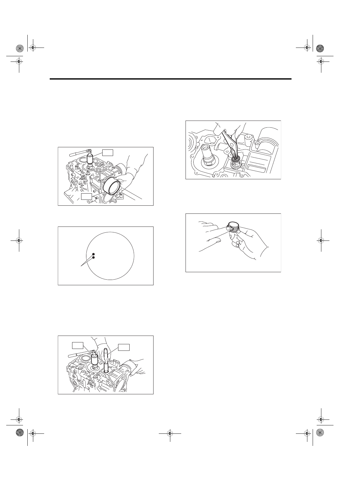
20) Install the piston.
(1) Set the parts so that the #1 and #2 cylinders
are on the upper side.
(2) Using the ST1, turn the crankshaft so that
#1 and #2 connecting rods are set at bottom
dead center.
ST1 499987500
CRANKSHAFT SOCKET
(3) Apply a coat of engine oil to the pistons and
cylinders and insert pistons in their cylinders us-
ing ST2.
ST2 498747300
PISTON GUIDE
NOTE:
Face the piston front mark towards the front of the
engine.
21) Install the piston pin.
(1) Apply a coat of engine oil to ST3.
(2) Insert ST3 into the service hole to align the
piston pin hole and the connecting rod small
end.
ST3 499017100
PISTON PIN GUIDE
(3) Apply a thin coat of engine oil to piston pin,
and insert the piston pin into piston and con-
necting rod through service hole.
(4) Install the snap ring.
NOTE:
Use new snap rings.
(5) Apply liquid gasket to the threaded portion
of the service hole plug.
Liquid gasket:
THREE BOND 1105 (Part No. 004403010) or
equivalent
(A) Front mark
ME-00157
ST2
ST1
ME-00742
(A)
ME-00158
ST1
ST3
ME-00159
ME-00160
ME(w/o STI)-86
Cylinder Block
MECHANICAL
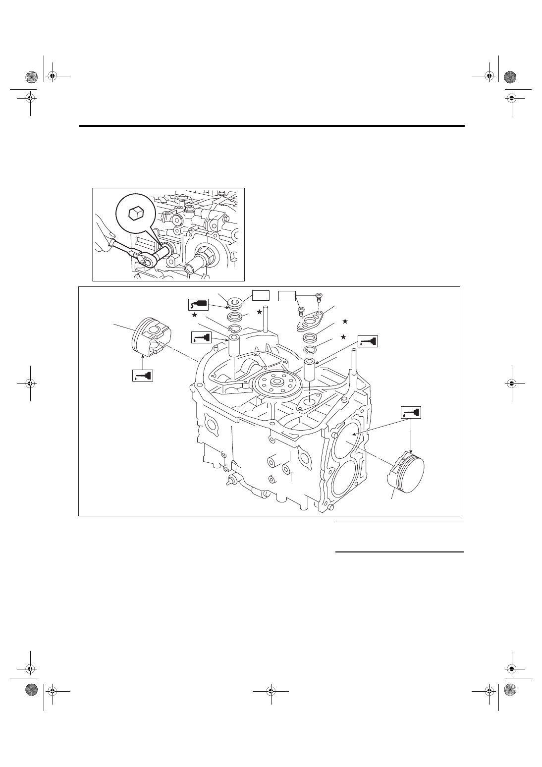
(6) Install the service hole plug and gasket.
NOTE:
Use a new gasket.
Tightening torque:
70 N·m (7.1 kgf-m, 51.6 ft-lb)
ME-00140
(1)
Piston
(5)
Service hole plug
Tightening torque: N·m (kgf-m, ft-lb)
(2)
Piston pin
(6)
Service hole cover
T1: 6.4 (0.7, 4.7)
(3)
Snap ring
(7)
O-ring
T2: 70 (7.1, 51.6)
(4)
Gasket
ME-05040
(2)
(3)
(1)
(2)
(6)
(3)
(7)
(4)
(5)
T2
T1
(1)
ME(w/o STI)-87
Cylinder Block
MECHANICAL
(7) Set the parts so that the #3 and #4 cylinders
are on the upper side. Following the same pro-
cedures as used for #1 and #2 cylinders, install
the pistons and piston pins.
(8) Install the service hole cover.
NOTE:
Use new O-rings.
Tightening torque:
6.4 N·m (0.7 kgf-m, 4.7 ft-lb)
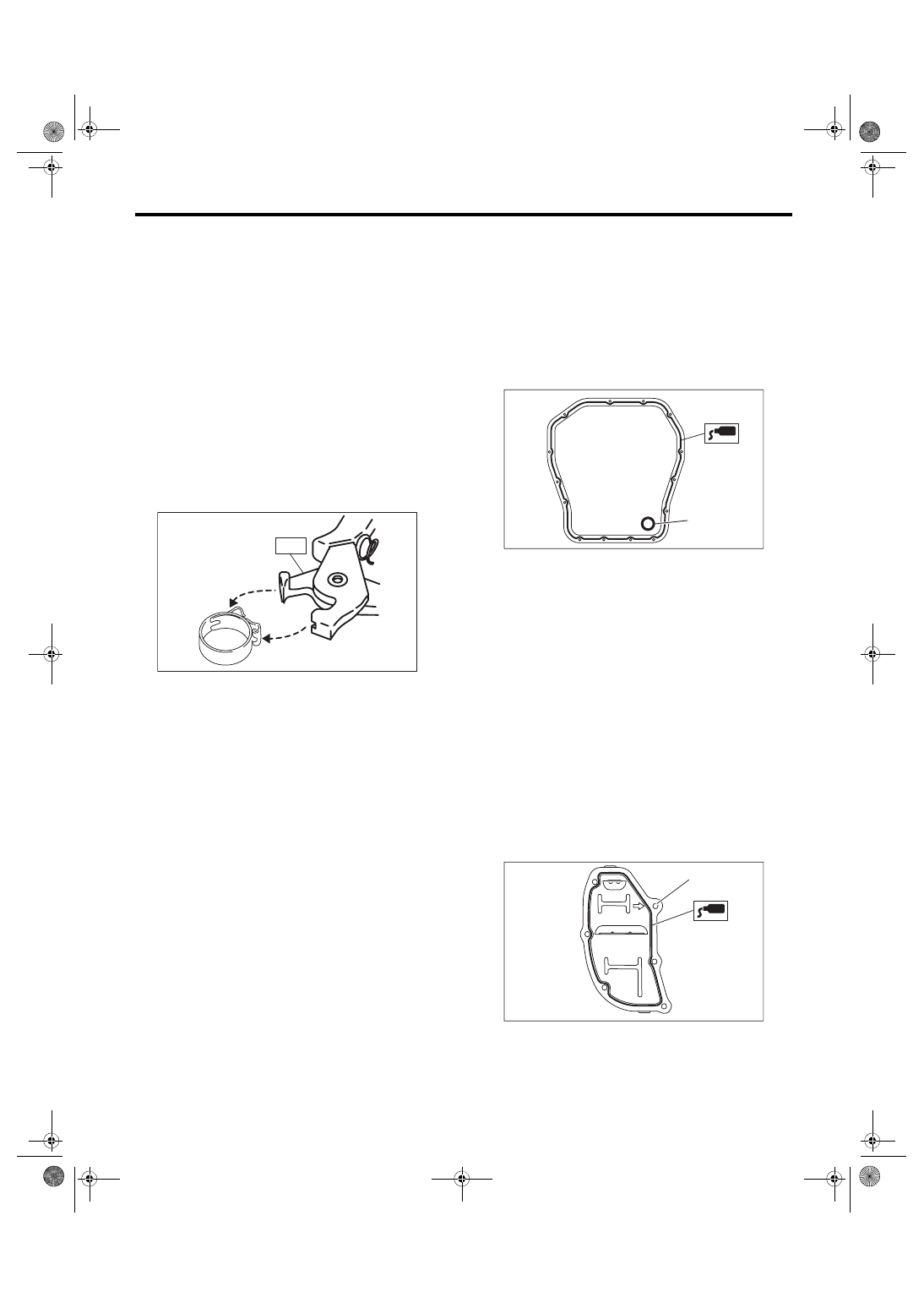
22) Install the water tank pipe assembly onto the
cylinder block RH.
NOTE:
Use a new clamp for the water tank pipe assembly
clamp, fit the cut out in the ST with the protrusion on
the clamp as shown in the figure, and lock the
clamp.
ST 18353AA000 CLAMP PLIERS
23) Install the baffle plate.
Tightening torque:
6.4 N·m (0.7 kgf-m, 4.7 ft-lb)
24) Install the oil strainer.
NOTE:
Use new O-rings.
Tightening torque:
10 N·m (1.0 kgf-m, 7.2 ft-lb)
25) Tighten the oil strainer stay together with the
baffle plate.
Tightening torque:
6.4 N·m (0.7 kgf-m, 4.7 ft-lb)
26) Apply liquid gasket to the mating surfaces of oil
pan, and install the oil pan.
NOTE:
Install within 5 min. after applying liquid gasket.
Liquid gasket:
THREE BOND 1217G (Part No. K0877Y0100)
or equivalent
Tightening torque:
5 N·m (0.5 kgf-m, 3.7 ft-lb)
27) Apply liquid gasket to the mating surface of oil
separator cover and the threaded portion of bolt (A)
shown in the figure (when reusing the bolt), and
then install the oil separator cover.
NOTE:
• Install within 5 min. after applying liquid gasket.
• Use new oil separator cover.
Liquid gasket:
Mating surface
THREE BOND 1217G (Part No.
K0877Y0100) or equivalent
Bolt thread (A) (when reusing the bolt)
THREE BOND 1324 (Part No. 004403042) or
equivalent
Tightening torque:
6.4 N·m (0.7 kgf-m, 4.7 ft-lb)
28) Install the flywheel. <Ref. to CL-14, INSTALLA-
29) Install the clutch disc and cover. <Ref. to CL-
11, INSTALLATION, Clutch Disc and Cover.>
ME-04374
ST
(A) Gasket
LU-02353
(A)
ME-03333
(A)
ME(w/o STI)-88
Cylinder Block
MECHANICAL
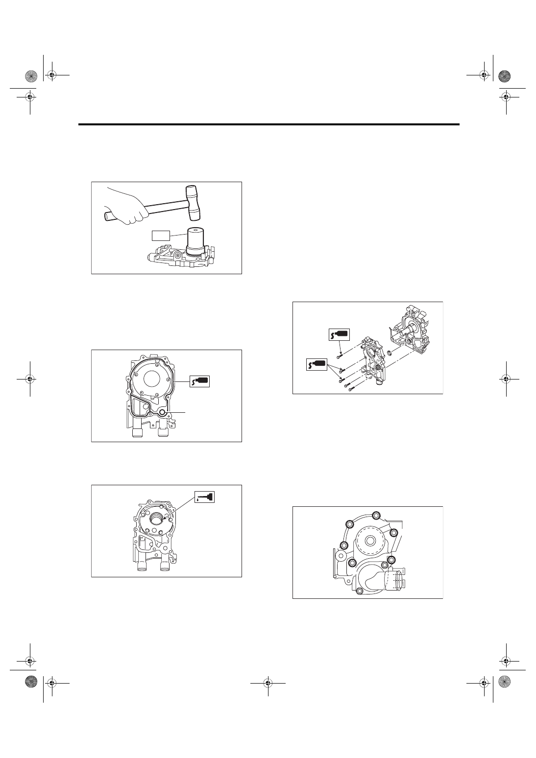
30) Install the oil pump.
(1) Using the ST, install the front oil seal.
ST 499587100
OIL SEAL INSTALLER
NOTE:
Use a new front oil seal.
(2) Apply liquid gasket to the mating surfaces of
oil pump.
NOTE:
Install within 5 min. after applying liquid gasket.
Liquid gasket:
THREE BOND 1217G (Part No. K0877Y0100)
or equivalent
(3) Apply a thin coat of engine oil to the inside of
front oil seal.
(4) Install the oil pump to cylinder block.
CAUTION:
• Be careful not to damage the front oil seal
during installation.
• Make sure the front oil seal lip is not folded.
NOTE:
• Align the flat surface of oil pump’s inner rotor with
that of crankshaft before installation.
• Use new O-rings.
• Do not forget to assemble O-rings.
(5) Apply liquid gasket to the three bolts thread
shown in figure. (when reusing bolts)
Liquid gasket:
THREE BOND 1324 (Part No. 004403042) or
equivalent
Tightening torque:
6.4 N·m (0.7 kgf-m, 4.7 ft-lb)
31) Install the water pump and gasket.
NOTE:
• When installing the water pump, tighten bolts in
two stages in alphabetical order as shown in the
figure.
• Use a new gasket.
Tightening torque:
First:
12 N·m (1.2 kgf-m, 8.9 ft-lb)
Second:
12 N·m (1.2 kgf-m, 8.9 ft-lb)
32) Install the water by-pass pipe for heater.
Tightening torque:
6.4 N·m (0.7 kgf-m, 4.7 ft-lb)
(A) O-ring
LU-00021
ST
ME-00165
(A)
ME-00312
ME-04946
ME-04743
(F)
(C)
(A)
(E)
(D)
(B)
Нет комментариевНе стесняйтесь поделиться с нами вашим ценным мнением.
Текст