Subaru Impreza 3 / Impreza WRX / Impreza WRX STI. Service manual — part 177
ME(w/o STI)-89
Cylinder Block
MECHANICAL
33) Install the oil filter. <Ref. to LU(STI)-31, IN-
STALLATION, Engine Oil Filter.>
34) Install the cylinder head. <Ref. to ME(w/o STI)-
68, INSTALLATION, Cylinder Head.>
35) Install the camshaft. <Ref. to ME(w/o STI)-61,
36) Install the generator and A/C compressor with
their brackets.
Tightening torque:
36 N·m (3.7 kgf-m, 26.6 ft-lb)
37) Install the crank sprocket. <Ref. to ME(w/o
STI)-58, INSTALLATION, Crank Sprocket.>
38) Install the cam sprocket. <Ref. to ME(w/o STI)-
57, INSTALLATION, Cam Sprocket.>
39) Install the timing belt. <Ref. to ME(w/o STI)-50,
40) Adjust the valve clearance. <Ref. to ME(w/o
STI)-28, ADJUSTMENT, Valve Clearance.>
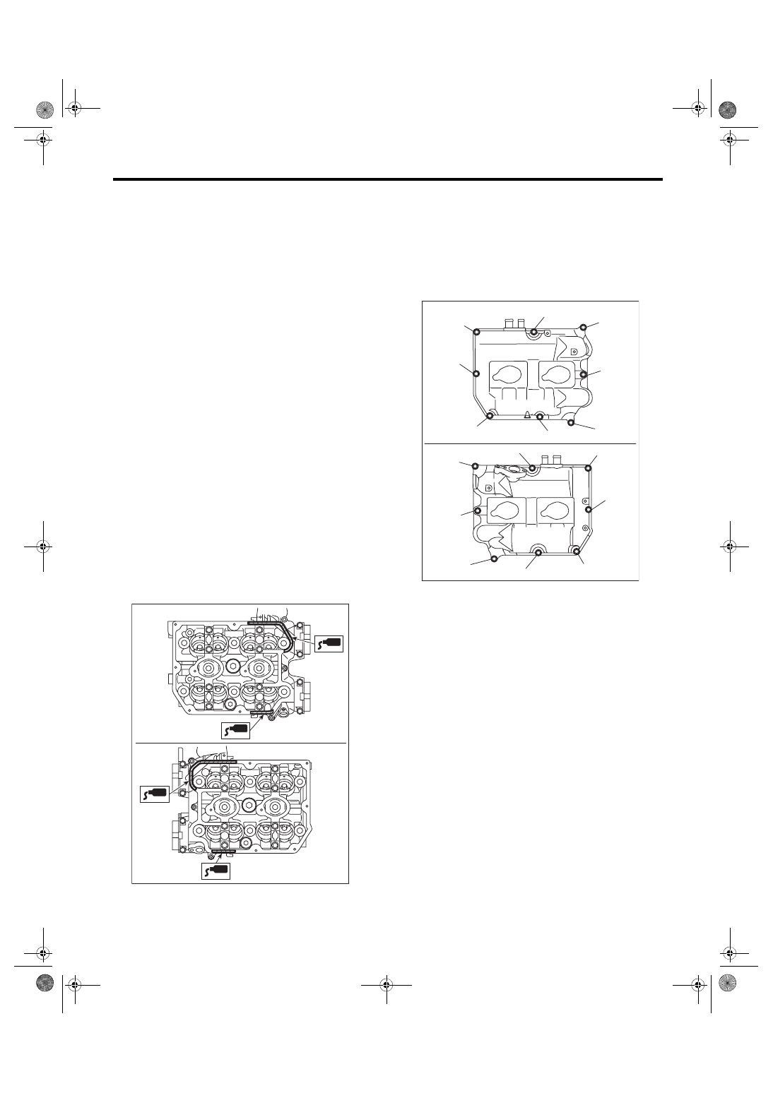
41) Install the rocker cover.
(1) Install the rocker cover gasket to the rocker
cover. (outer section and ignition coil section)
NOTE:
Use a new rocker cover gasket.
(2) Apply liquid gasket to the specified point of
the cylinder head.
NOTE:
Install within 5 min. after applying liquid gasket.
Liquid gasket:
THREE BOND 1217G (Part No. K0877Y0100)
or equivalent
(3) Install the rocker cover onto cylinder heads.
Ensure the gasket is properly positioned during
installation.
(4) Temporarily tighten the rocker cover bolts in
alphabetical order shown in the figure, and then
tighten to specified torque in alphabetical order.
Tightening torque:
6.4 N·m (0.7 kgf-m, 4.7 ft-lb)
ME-05981
ME-05982
(E)
(F)
(H)
(G)
(D),(L)
(A),(I)
(C),(K)
(B),(J)
(B),(J)
(H)
(F)
(C),(K)
(E)
(A),(I)
(D),(L)
(G)
ME(w/o STI)-90
Cylinder Block
MECHANICAL
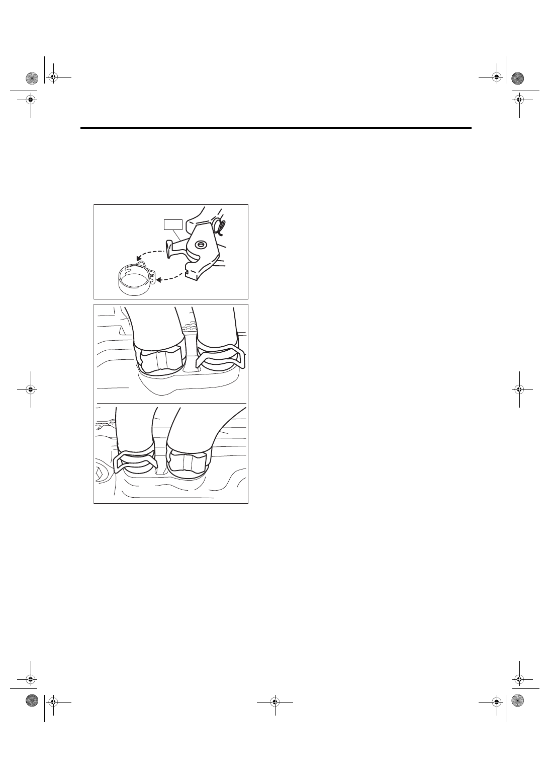
42) Connect the PCV hose (A) and PCV hose as-
sembly (B) to the rocker cover.
NOTE:
Use a new clamp for the PCV hose (A), fit the cut
out in the ST with the protrusion on the clamp as
shown in the figure, and lock the clamp.
ST 18353AA000 CLAMP PLIERS
43) Install the timing belt cover. <Ref. to ME(w/o
STI)-47, INSTALLATION, Timing Belt Cover.>
44) Install the crank pulley. <Ref. to ME(w/o STI)-
45, INSTALLATION, Crank Pulley.>
45) Install the intake manifold. <Ref. to FU(w/o
STI)-22, INSTALLATION, Intake Manifold.>
46) Install the rear side belt. <Ref. to ME(w/o STI)-
39, REAR SIDE BELT, INSTALLATION, V-belt.>
47) Install the engine to the vehicle. <Ref. to ME(w/
o STI)-33, INSTALLATION, Engine Assembly.>
ME-04374
ST
ME-05768
(A)
(B)
(A)
(B)
ME(w/o STI)-91
Cylinder Block
MECHANICAL
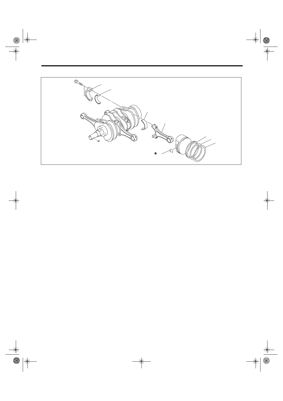
C: DISASSEMBLY
1) Remove the connecting rod cap.
2) Remove the connecting rod bearing.
NOTE:
Keep the removed connecting rods, connecting rod
caps and bearings in order so that they are kept in
their original combinations/groups, and not mixed
together.
3) Remove the piston rings using piston ring ex-
pander.
4) Remove the oil ring by hand.
NOTE:
Arrange the removed piston rings in proper order,
to prevent confusion.
5) Remove the snap ring.
(1)
Top ring
(4)
Snap ring
(6)
Connecting rod bearing
(2)
Second ring
(5)
Connecting rod
(7)
Connecting rod cap
(3)
Oil ring
ME-04831
(6)
(6)
(4)
(3)
(2)
(1)
(7)
(5)
ME(w/o STI)-92
Cylinder Block
MECHANICAL
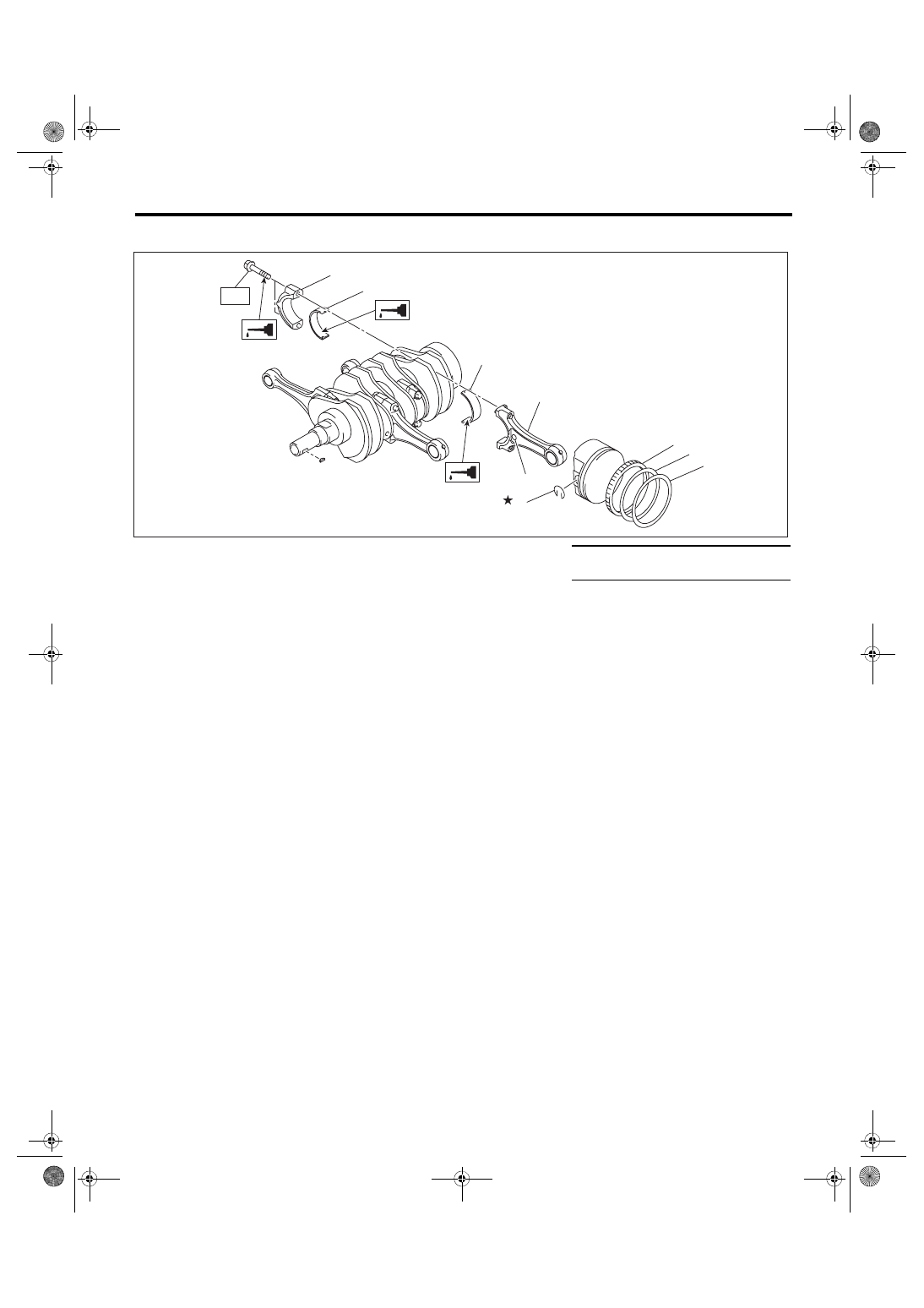
D: ASSEMBLY
1) Apply engine oil to the surface of the connecting
rod bearings, and install the connecting rod bear-
ings on connecting rods and connecting rod caps.
2) Position each connecting rod with the side with a
side mark facing forward, and install it.
3) Attach the connecting rod cap and tighten it with
connecting rod bolt. Make sure the arrow on con-
necting rod cap faces the front during installation.
NOTE:
• Each connecting rod has its own mating cap.
Make sure that they are assembled correctly by
checking their matching number.
• When tightening the connecting rod bolts, apply
oil on the threads.
Tightening torque:
52 N·m (5.3 kgf-m, 38.4 ft-lb)
4) Install the oil ring upper rail, expander and lower
rail by hand.
5) Install the second ring and top ring using piston
ring expander.
NOTE:
Assemble so that the piston ring mark “R” faces the
top side of the piston.
E: INSPECTION
1. CYLINDER BLOCK
1) Check for cracks or damage. Use liquid pene-
trant tester on the important sections to check for
fissures. Check that there are no marks of gas leak-
ing or water leaking on gasket installing surface.
2) Check the oil passages for clogging.
3) Inspect the cylinder head surface that mates
with cylinder block for warping by using a straight
edge, and correct by grinding if necessary.
Warping limit:
0.025 mm (0.00098 in)
Grinding limit:
0.1 mm (0.004 in)
Standard height of cylinder block:
201.0 mm (7.91 in)
(1)
Top ring
(5)
Side mark
Tightening torque: N·m (kgf-m, ft-lb)
(2)
Second ring
(6)
Connecting rod
T: 52 (5.3, 38.4)
(3)
Oil ring
(7)
Connecting rod bearing
(4)
Snap ring
(8)
Connecting rod cap
ME-04832
(7)
(7)
(4)
(3)
(2)
(1)
(8)
(6)
(5)
T
Нет комментариевНе стесняйтесь поделиться с нами вашим ценным мнением.
Текст