Subaru Impreza 3 / Impreza WRX / Impreza WRX STI. Service manual — part 248

EN(H4DOTC)(diag)-216
Diagnostic Procedure with Diagnostic Trouble Code (DTC)
ENGINE (DIAGNOSTICS)
BQ:DTC P0346 CAMSHAFT POSITION SENSOR "A" CIRCUIT RANGE/PERFOR-
MANCE (BANK 2)
NOTE:
For the diagnostic procedure, refer to DTC P0345. <Ref. to EN(H4DOTC)(diag)-214, DTC P0345 CAM-
SHAFT POSITION SENSOR “A” CIRCUIT (BANK 2), Diagnostic Procedure with Diagnostic Trouble Code
6
CHECK CAMSHAFT POSITION SENSOR.
Check the waveform of the camshaft position
sensor. <Ref. to EN(H4DOTC)(diag)-23,
Engine Control Module (ECM) I/O Signal.>
Is there any abnormality in
waveform?
Repair the follow-
ing item.
• Poor contact of
ECM connector
• Poor contact of
camshaft position
sensor connector
• Poor contact of
coupling connector
Step
Check
Yes
No
EN(H4DOTC)(diag)-217
Diagnostic Procedure with Diagnostic Trouble Code (DTC)
ENGINE (DIAGNOSTICS)
BR:DTC P0351 IGNITION COIL A PRIMARY/SECONDARY CIRCUIT
DTC DETECTING CONDITION:
• Immediately at fault recognition
• GENERAL DESCRIPTION <Ref. to GD(H4DOTC)-136, DTC P0351 IGNITION COIL A PRIMARY/SEC-
ONDARY CIRCUIT, Diagnostic Trouble Code (DTC) Detecting Criteria.>
TROUBLE SYMPTOM:
• Improper idling
• Poor driving performance
CAUTION:
After servicing or replacing faulty parts, perform Clear Memory Mode <Ref. to EN(H4DOTC)(diag)-63,
OPERATION, Clear Memory Mode.>, and Inspection Mode <Ref. to EN(H4DOTC)(diag)-49, PROCE-
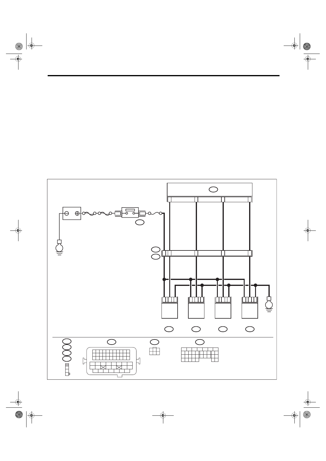
WIRING DIAGRAM:
• Engine electrical system, without SI-DRIVE <Ref. to WI-32, WITHOUT SI-DRIVE, WIRING DIAGRAM,
• Engine electrical system, with SI-DRIVE <Ref. to WI-48, WITH SI-DRIVE, WIRING DIAGRAM, Engine
ECM
EN-08716
B72
B134
21
22
31
32
1
3
E2
B21
E31
E32
E33
E34
E34
E33
E32
E31
1
2
3
B21
3
1
2
3
1
2
9
49
20
31
10
3
1
2
3
1
2
B72
1 2 3 4
12 13 14 15
5 6 7 8
16 17 18 19
9 10 11
20 21 22
23 24 25 26 27 28 29 30 31 32 33
35
34
37
36
39
38
41
40
43
42
44 45
47
46
49
48
51
50
53
52
54
B134
31
30
32
29
34
33
21
20
19
18
17
16
28
27
26
15
14
13
12
11
25
23
22
24
10
3
4
9
1
2
8
7
6
5
2
6
5
4
3
1
SBF-6
E
E
IGNITION COIL
No. 2
IGNITION COIL
No. 4
IGNITION COIL
No. 3
IGNITION COIL
No. 1
IGNITION
SWITCH
No. 12
MAIN
SBF
BATTERY
EN(H4DOTC)(diag)-218
Diagnostic Procedure with Diagnostic Trouble Code (DTC)
ENGINE (DIAGNOSTICS)
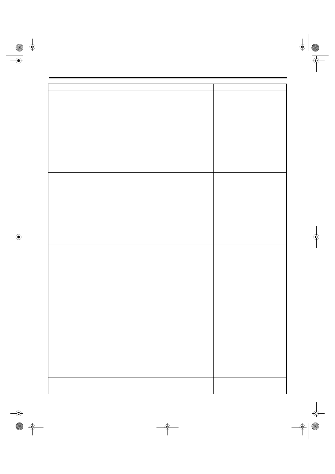
Step
Check
Yes
No
1
CHECK IGNITION COIL POWER SUPPLY
CIRCUIT.
1) Turn the ignition switch to OFF.
2) Disconnect the connector from ignition coil.
3) Turn the ignition switch to ON.
4) Measure the voltage between ignition coil
connector and engine ground.
Connector & terminal
DTC P0351; (E31) No. 3 (+) — Engine
ground (–):
DTC P0352; (E32) No. 3 (+) — Engine
ground (–):
DTC P0353; (E33) No. 3 (+) — Engine
ground (–):
DTC P0354; (E34) No. 3 (+) — Engine
ground (–):
Is the voltage 10 V or more?
Repair the harness
and connector.
NOTE:
In this case, repair
the following item:
• Open circuit or
short circuit to
ground in harness
of power supply
circuit
• Blown out of fuse
• Poor contact of
coupling connector
2
CHECK HARNESS OF IGNITION COIL
GROUND CIRCUIT.
1) Turn the ignition switch to OFF.
2) Measure the resistance of harness between
ignition coil connector and engine ground.
Connector & terminal
DTC P0351; (E31) No. 2 — Engine
ground:
DTC P0352; (E32) No. 2 — Engine
ground:
DTC P0353; (E33) No. 2 — Engine
ground:
DTC P0354; (E34) No. 2 — Engine
ground:
Is the resistance less than 5 Ω? Go to step
Repair the open
circuit in harness
between ignition
coil connector and
engine grounding
terminal.
3
CHECK HARNESS BETWEEN ECM AND IG-
NITION COIL CONNECTOR.
1) Disconnect the connector from ECM.
2) Measure the resistance between ignition
coil connector and engine ground.
Connector & terminal
DTC P0351; (E31) No. 1 — Engine
ground:
DTC P0352; (E32) No. 1 — Engine
ground:
DTC P0353; (E33) No. 1 — Engine
ground:
DTC P0354; (E34) No. 1 — Engine
ground:
Is the resistance 1 MΩ or
more?
Repair the ground
short circuit of har-
ness between
ECM connector
and ignition coil
connector.
4
CHECK HARNESS BETWEEN ECM AND IG-
NITION COIL CONNECTOR.
Measure the resistance of harness between
ECM connector and ignition coil connector.
Connector & terminal
DTC P0351; (B134) No. 21 — (E31) No. 1:
DTC P0352; (B134) No. 22 — (E32) No. 1:
DTC P0353; (B134) No. 31 — (E33) No. 1:
DTC P0354; (B134) No. 32 — (E34) No. 1:
Is the resistance less than 1 Ω? Go to step
Repair the harness
and connector.
NOTE:
In this case, repair
the following item:
• Open circuit of
harness between
ECM
connector
and the ignition coil
connector
• Poor contact of
coupling connector
5
CHECK FOR POOR CONTACT.
Check for poor contact of ECM connector.
Is there poor contact of ECM
connector?
Repair the poor
contact of ECM
connector.

EN(H4DOTC)(diag)-219
Diagnostic Procedure with Diagnostic Trouble Code (DTC)
ENGINE (DIAGNOSTICS)
BS:DTC P0352 IGNITION COIL B PRIMARY/SECONDARY CIRCUIT
NOTE:
For the diagnostic procedure, refer to DTC P0351. <Ref. to EN(H4DOTC)(diag)-217, DTC P0351 IGNITION
COIL A PRIMARY/SECONDARY CIRCUIT, Diagnostic Procedure with Diagnostic Trouble Code (DTC).>
BT:DTC P0353 IGNITION COIL C PRIMARY/SECONDARY CIRCUIT
NOTE:
For the diagnostic procedure, refer to DTC P0351. <Ref. to EN(H4DOTC)(diag)-217, DTC P0351 IGNITION
COIL A PRIMARY/SECONDARY CIRCUIT, Diagnostic Procedure with Diagnostic Trouble Code (DTC).>
BU:DTC P0354 IGNITION COIL D PRIMARY/SECONDARY CIRCUIT
NOTE:
For the diagnostic procedure, refer to DTC P0351. <Ref. to EN(H4DOTC)(diag)-217, DTC P0351 IGNITION
COIL A PRIMARY/SECONDARY CIRCUIT, Diagnostic Procedure with Diagnostic Trouble Code (DTC).>
6
Is the spark plug condition nor-
mal?
Replace the spark
plug. <Ref. to
IG(STI)-4, Spark
Plug.> <Ref. to
IG(w/o STI)-5,
Spark Plug.>
Step
Check
Yes
No
Нет комментариевНе стесняйтесь поделиться с нами вашим ценным мнением.
Текст