Subaru Impreza 3 / Impreza WRX / Impreza WRX STI. Service manual — part 246
EN(H4DOTC)(diag)-208
Diagnostic Procedure with Diagnostic Trouble Code (DTC)
ENGINE (DIAGNOSTICS)
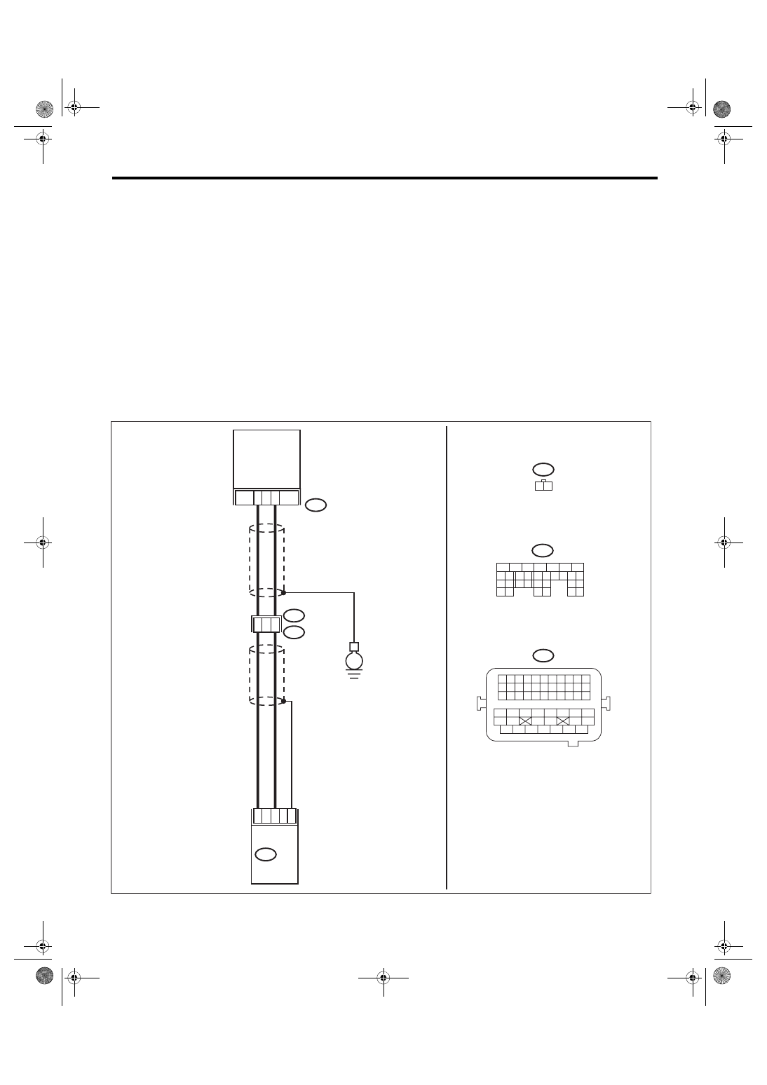
BL:DTC P0335 CRANKSHAFT POSITION SENSOR “A” CIRCUIT
DTC DETECTING CONDITION:
• Immediately at fault recognition
• GENERAL DESCRIPTION <Ref. to GD(H4DOTC)-128, DTC P0335 CRANKSHAFT POSITION SENSOR
“A” CIRCUIT, Diagnostic Trouble Code (DTC) Detecting Criteria.>
TROUBLE SYMPTOM:
• Engine stalls.
• Failure of engine to start
CAUTION:
After servicing or replacing faulty parts, perform Clear Memory Mode <Ref. to EN(H4DOTC)(diag)-63,
OPERATION, Clear Memory Mode.>, and Inspection Mode <Ref. to EN(H4DOTC)(diag)-49, PROCE-
WIRING DIAGRAM:
• Engine electrical system, without SI-DRIVE <Ref. to WI-32, WITHOUT SI-DRIVE, WIRING DIAGRAM,
• Engine electrical system, with SI-DRIVE <Ref. to WI-48, WITH SI-DRIVE, WIRING DIAGRAM, Engine
ECM
EN-08731
1
2
14
3
25
31
E10
B21
B137
31
30
29
28
27
21
20
19
18
17
16
26
25
24
15
14
13
12
11
23
22
10
3
4
9
1
2
8
7
6
5
33
32
31
30
29
28
27
26
47
46
45
44
43
42
54
53
52
51
50
49
48
41
40
39
38
37
36
35
34
25
24
23
22
21
20
19
18
17
16
15
14
13
12
11
10
9
8
7
6
5
4
3
2
1
17
B137
2
1
E10
E2
B21
E
CRANKSHAFT
POSITION
SENSOR

EN(H4DOTC)(diag)-209
Diagnostic Procedure with Diagnostic Trouble Code (DTC)
ENGINE (DIAGNOSTICS)
Step
Check
Yes
No
1
CHECK CONDITION OF CRANKSHAFT PO-
SITION SENSOR.
Is the crankshaft position sen-
sor installation bolt tightened
securely?
2
CHECK CRANKSHAFT POSITION SENSOR.
1) Turn the ignition switch to OFF.
2) Remove the crankshaft position sensor.
3) Measure the resistance between terminals
of crankshaft position sensor.
Terminals
No. 1 — No. 2:
Is the resistance between 1 and
4 kΩ?
3
CHECK HARNESS BETWEEN ECM AND
CRANKSHAFT POSITION SENSOR CON-
NECTOR.
1) Disconnect the connector from ECM.
2) Measure the resistance of harness between
ECM connector and crankshaft position sensor
connector.
Connector & terminal
(B137) No. 17 — (E10) No. 1:
(B137) No. 25 — (E10) No. 2:
Is the resistance less than 1 Ω? Repair the poor
contact of ECM
and crankshaft
position sensor
connector.
Repair the harness
and connector.
NOTE:
In this case, repair
the following item:
• Open circuit in
harness between
ECM
connector
and crankshaft po-
sition sensor con-
nector
• Poor contact of
coupling connector

EN(H4DOTC)(diag)-210
Diagnostic Procedure with Diagnostic Trouble Code (DTC)
ENGINE (DIAGNOSTICS)
BM:DTC P0336 CRANKSHAFT POSITION SENSOR “A” CIRCUIT RANGE/PER-
FORMANCE
DTC DETECTING CONDITION:
• Detected when two consecutive driving cycles with fault occur.
• GENERAL DESCRIPTION <Ref. to GD(H4DOTC)-130, DTC P0336 CRANKSHAFT POSITION SENSOR
“A” CIRCUIT RANGE/PERFORMANCE, Diagnostic Trouble Code (DTC) Detecting Criteria.>
TROUBLE SYMPTOM:
• Engine stalls.
• Failure of engine to start
CAUTION:
After servicing or replacing faulty parts, perform Clear Memory Mode <Ref. to EN(H4DOTC)(diag)-63,
OPERATION, Clear Memory Mode.>, and Inspection Mode <Ref. to EN(H4DOTC)(diag)-49, PROCE-
Step
Check
Yes
No
1
CHECK CONDITION OF CRANKSHAFT PO-
SITION SENSOR.
Turn the ignition switch to OFF.
Is the crankshaft position sen-
sor installation bolt tightened
securely?
2
CHECK CRANK SPROCKET.
Remove the timing belt cover.
Are crank sprocket teeth
cracked or damaged?
3
CHECK INSTALLATION CONDITION OF
TIMING BELT.
Turn the crankshaft, and align alignment mark
on crank sprocket with alignment mark on cylin-
der block.
ST 499987500
CRANKSHAFT
SOCKET
Is the timing belt dislocated
from its proper position?
EN(H4DOTC)(diag)-211
Diagnostic Procedure with Diagnostic Trouble Code (DTC)
ENGINE (DIAGNOSTICS)
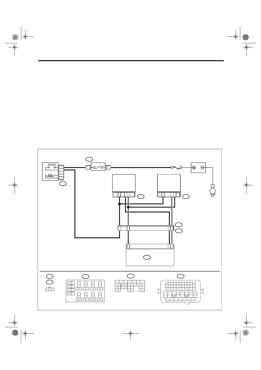
BN:DTC P0340 CAMSHAFT POSITION SENSOR “A” CIRCUIT (BANK 1 OR SIN-
GLE SENSOR)
DTC DETECTING CONDITION:
• Immediately at fault recognition
• GENERAL DESCRIPTION <Ref. to GD(H4DOTC)-132, DTC P0340 CAMSHAFT POSITION SENSOR
“A” CIRCUIT (BANK 1 OR SINGLE SENSOR), Diagnostic Trouble Code (DTC) Detecting Criteria.>
TROUBLE SYMPTOM:
• Engine stalls.
• Failure of engine to start
CAUTION:
After servicing or replacing faulty parts, perform Clear Memory Mode <Ref. to EN(H4DOTC)(diag)-63,
OPERATION, Clear Memory Mode.>, and Inspection Mode <Ref. to EN(H4DOTC)(diag)-49, PROCE-
WIRING DIAGRAM:
• Engine electrical system, without SI-DRIVE <Ref. to WI-32, WITHOUT SI-DRIVE, WIRING DIAGRAM,
• Engine electrical system, with SI-DRIVE <Ref. to WI-48, WITH SI-DRIVE, WIRING DIAGRAM, Engine
ECM
EN-08732
3
30
E35
E2
B21
2
E36
1
3
24
2
1
B137
E36
1 2 3
E35
16
B21
1 2 3 4
12 13 14 15
5 6 7 8
16 17 18 19
9 10 11
20 21 22
23 24 25 26 27 28 29 30 31 32 33
35
34
37
36
39
38
41
40
43
42
44 45
47
46
49
48
51
50
53
52
54
5
4
8
2
13
B220
24
23
22
21
B137
31
30
29
28
27
21
20
19
18
17
16
26
25
24
15
14
13
12
11
23
22
10
3
4
9
1
2
8
7
6
5
B220
18
19
6
7
4
3
5
2
1
12
11
10
9
8
40
36 39
38
37
34
33
35
32
28 31
30
29
23
22
21
20
26
25
24
27
17
16
15
14
13
4
3
B220
15A
SBF-7
E
FUSE
(RELAY BLOCK)
MAIN RELAY
INTAKE
CAMSHAFT
POSITION
SENSOR LH
INTAKE
CAMSHAFT
POSITION
SENSOR RH
BATTERY
Нет комментариевНе стесняйтесь поделиться с нами вашим ценным мнением.
Текст