Subaru Impreza 3 / Impreza WRX / Impreza WRX STI. Service manual — part 249
EN(H4DOTC)(diag)-220
Diagnostic Procedure with Diagnostic Trouble Code (DTC)
ENGINE (DIAGNOSTICS)
BV:DTC P0365 CAMSHAFT POSITION SENSOR “B” CIRCUIT (BANK 1)
DTC DETECTING CONDITION:
• Immediately at fault recognition
• GENERAL DESCRIPTION <Ref. to GD(H4DOTC)-137, DTC P0365 CAMSHAFT POSITION SENSOR
“B” CIRCUIT (BANK 1), Diagnostic Trouble Code (DTC) Detecting Criteria.>
TROUBLE SYMPTOM:
• Engine stalls.
• Failure of engine to start
CAUTION:
After servicing or replacing faulty parts, perform Clear Memory Mode <Ref. to EN(H4DOTC)(diag)-63,
OPERATION, Clear Memory Mode.>, and Inspection Mode <Ref. to EN(H4DOTC)(diag)-49, PROCE-
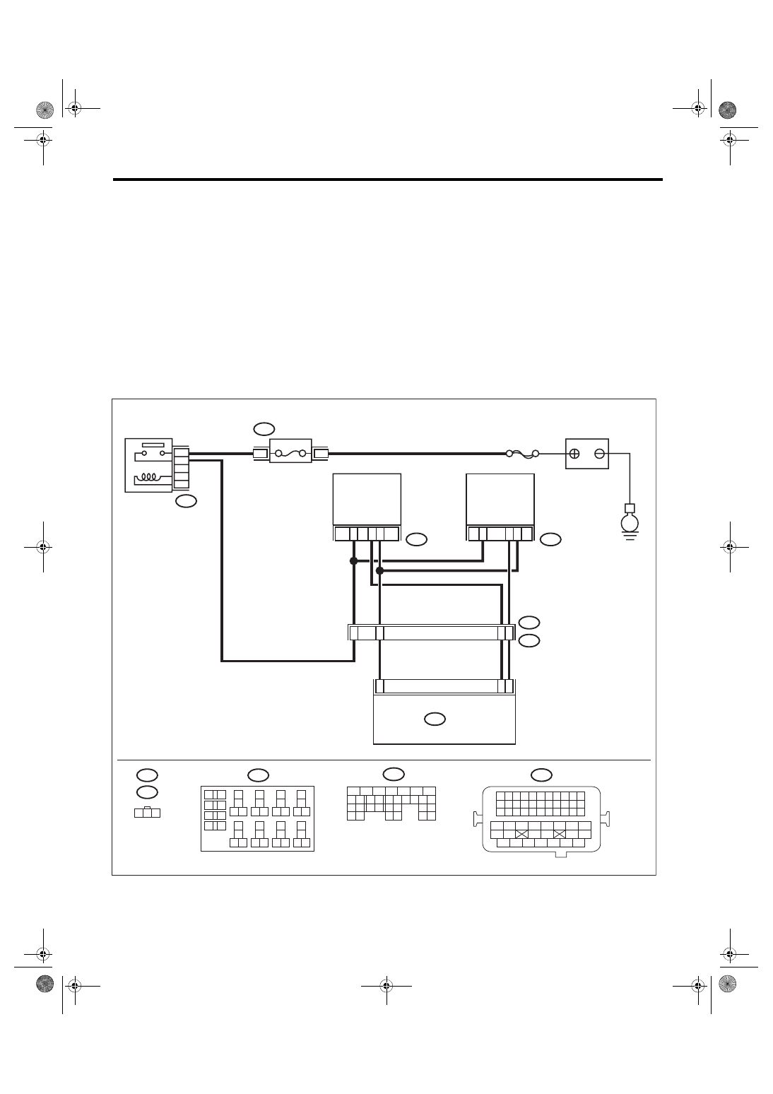
WIRING DIAGRAM:
Engine electrical system, with SI-DRIVE <Ref. to WI-48, WITH SI-DRIVE, WIRING DIAGRAM, Engine Elec-
EN-08733
3
30
2
E62
1
3
23
2
1
B137
E65
1 2 3
E62
29
B21
1 2 3 4
12 13 14 15
5 6 7 8
16 17 18 19
9 10 11
20 21 22
23 24 25 26 27 28 29 30 31 32 33
35
34
37
36
39
38
41
40
43
42
44 45
47
46
49
48
51
50
53
52
54
E65
E2
B21
5
4
8
15
26
B220
24
23
22
21
B137
31
30
29
28
27
21
20
19
18
17
16
26
25
24
15
14
13
12
11
23
22
10
3
4
9
1
2
8
7
6
5
B220
18
19
6
7
4
3
5
2
1
12
11
10
9
8
40
36 39
38
37
34
33
35
32
28 31
30
29
23
22
21
20
26
25
24
27
17
16
15
14
13
4
3
B220
15A
E
ECM
SBF-7
FUSE
(RELAY BLOCK)
MAIN RELAY
EXHAUST
CAMSHAFT
POSITION
SENSOR LH
EXHAUST
CAMSHAFT
POSITION
SENSOR RH
BATTERY

EN(H4DOTC)(diag)-221
Diagnostic Procedure with Diagnostic Trouble Code (DTC)
ENGINE (DIAGNOSTICS)
Step
Check
Yes
No
1
CHECK POWER SUPPLY OF CAMSHAFT
POSITION SENSOR.
1) Turn the ignition switch to OFF.
2) Disconnect the connector from camshaft
position sensor.
3) Turn the ignition switch to ON.
4) Measure the voltage between camshaft
position sensor connector and engine ground.
Connector & terminal
(E62) No. 1 (+) — Engine ground (–):
Is the voltage 10 V or more?
Repair the harness
and connector.
NOTE:
In this case, repair
the following item:
• Open circuit or
short circuit to
ground in harness
between main re-
lay connector and
camshaft position
sensor connector
• Poor contact of
coupling connector
2
CHECK HARNESS BETWEEN ECM AND
CAMSHAFT POSITION SENSOR CONNEC-
TOR.
1) Turn the ignition switch to OFF.
2) Disconnect the connector from ECM.
3) Measure the resistance between ECM con-
nector and camshaft position sensor connector.
Connector & terminal
(B137) No. 23 — (E62) No. 2:
(B137) No. 30 — (E62) No. 3:
Is the resistance less than 1 Ω? Go to step
Repair the harness
and connector.
NOTE:
In this case, repair
the following item:
• Open circuit in
harness between
ECM
connector
and camshaft posi-
tion sensor con-
nector
• Poor contact of
coupling connector
3
CHECK HARNESS BETWEEN ECM AND
CAMSHAFT POSITION SENSOR CONNEC-
TOR.
Measure the resistance between camshaft
position sensor connector and engine ground.
Connector & terminal
(E62) No. 2 — Engine ground:
Is the resistance 1 MΩ or
more?
Repair short circuit
to ground in har-
ness between
ECM connector
and camshaft posi-
tion sensor con-
nector.
4
CHECK HARNESS BETWEEN ECM AND
CAMSHAFT POSITION SENSOR CONNEC-
TOR.
Measure the voltage between camshaft posi-
tion sensor connector and engine ground.
Connector & terminal
(E62) No. 2 (+) — Engine ground (–):
Is the voltage 5 V or more?
Repair the short
circuit to power in
the harness
between ECM con-
nector and cam-
shaft position
sensor connector.
5
CHECK CONDITION OF CAMSHAFT POSI-
TION SENSOR.
Is the camshaft position sensor
installation bolt tightened
securely?
6
CHECK CAMSHAFT POSITION SENSOR.
Check the waveform of the camshaft position
sensor. <Ref. to EN(H4DOTC)(diag)-23,
Engine Control Module (ECM) I/O Signal.>
Is there any abnormality in
waveform?
Replace the cam-
shaft position sen-
sor. <Ref. to
FU(STI)-37, Cam-
shaft Position Sen-
sor.>
Repair the follow-
ing item.
• Poor contact of
ECM connector
• Poor contact of
camshaft position
sensor connector
• Poor contact of
coupling connector
EN(H4DOTC)(diag)-222
Diagnostic Procedure with Diagnostic Trouble Code (DTC)
ENGINE (DIAGNOSTICS)
BW:DTC P0366 CAMSHAFT POSITION SENSOR B CIRCUIT RANGE/PERFOR-
MANCE (BANK 1)
NOTE:
For the diagnostic procedure, refer to DTC P0365. <Ref. to EN(H4DOTC)(diag)-220, DTC P0365 CAM-
SHAFT POSITION SENSOR “B” CIRCUIT (BANK 1), Diagnostic Procedure with Diagnostic Trouble Code

EN(H4DOTC)(diag)-223
Diagnostic Procedure with Diagnostic Trouble Code (DTC)
ENGINE (DIAGNOSTICS)
BX:DTC P0390 CAMSHAFT POSITION SENSOR “B” CIRCUIT (BANK 2)
DTC DETECTING CONDITION:
• Immediately at fault recognition
• GENERAL DESCRIPTION <Ref. to GD(H4DOTC)-138, DTC P0390 CAMSHAFT POSITION SENSOR
“B” CIRCUIT (BANK 2), Diagnostic Trouble Code (DTC) Detecting Criteria.>
TROUBLE SYMPTOM:
• Engine stalls.
• Failure of engine to start
CAUTION:
After servicing or replacing faulty parts, perform Clear Memory Mode <Ref. to EN(H4DOTC)(diag)-63,
OPERATION, Clear Memory Mode.>, and Inspection Mode <Ref. to EN(H4DOTC)(diag)-49, PROCE-
WIRING DIAGRAM:
Engine electrical system, with SI-DRIVE <Ref. to WI-48, WITH SI-DRIVE, WIRING DIAGRAM, Engine Elec-
EN-08733
3
30
2
E62
1
3
23
2
1
B137
E65
1 2 3
E62
29
B21
1 2 3 4
12 13 14 15
5 6 7 8
16 17 18 19
9 10 11
20 21 22
23 24 25 26 27 28 29 30 31 32 33
35
34
37
36
39
38
41
40
43
42
44 45
47
46
49
48
51
50
53
52
54
E65
E2
B21
5
4
8
15
26
B220
24
23
22
21
B137
31
30
29
28
27
21
20
19
18
17
16
26
25
24
15
14
13
12
11
23
22
10
3
4
9
1
2
8
7
6
5
B220
18
19
6
7
4
3
5
2
1
12
11
10
9
8
40
36 39
38
37
34
33
35
32
28 31
30
29
23
22
21
20
26
25
24
27
17
16
15
14
13
4
3
B220
15A
E
ECM
SBF-7
FUSE
(RELAY BLOCK)
MAIN RELAY
EXHAUST
CAMSHAFT
POSITION
SENSOR LH
EXHAUST
CAMSHAFT
POSITION
SENSOR RH
BATTERY
Нет комментариевНе стесняйтесь поделиться с нами вашим ценным мнением.
Текст