Subaru Impreza 3 / Impreza WRX / Impreza WRX STI. Service manual — part 599
HVAC SYSTEM (AUTO A/C) (DIAGNOSTICS)
AC(diag)
Page
Basic Diagnostic Procedure . . . . . . . . . . . . . . . . . ...2
General Description . . . . . . . . . . . . . . . . . . . . ...3
Electrical Component Location . . . . . . . . . . . . . . . . ..5
Auto A/C Control Module I/O Signal . . . . . . . . . . . . . . ...7
Diagnostic Chart for Self-Diagnosis . . . . . . . . . . . . . . ...9
Diagnostics for A/C System Malfunction . . . . . . . . . . . . ..13
Diagnostic Procedure for Actuators . . . . . . . . . . . . . . .24
Diagnostic Procedure for Sensors . . . . . . . . . . . . . . ...29
Diagnostics with Phenomenon . . . . . . . . . . . . . . . . .37
AC(diag)-2
Basic Diagnostic Procedure
HVAC SYSTEM (AUTO A/C) (DIAGNOSTICS)
1. Basic Diagnostic Procedure
A: PROCEDURE
Step
Check
Yes
No
1
Does the self-diagnosis oper-
ate?
2
IDENTIFY MALFUNCTION PART.
Identify the malfunction part with self-diagnosis.
Can the malfunction part be
confirmed?
Repair the mal-
functioning part in
accordance with
each diagnostic
chart.
3
CHECK COMPARTMENT TEMPERATURE.
1) Turn the A/C switch to ON.
2) Turn the temperature control dial at maxi-
mum cool position.
3) Check the compartment temperature
change.
Does the compartment temper-
ature change?
<Ref. to AC-18,
PROCEDURE,
Refrigerant Pres-
sure with Manifold
Gauge Set.>
4
CHECK A/C SYSTEM RESPONSE.
Change the temperature setting, and check the
response of A/C system.
Does the A/C system respond
quickly?
A/C system is nor-
mal.
AC(diag)-3
General Description
HVAC SYSTEM (AUTO A/C) (DIAGNOSTICS)
2. General Description
A: CAUTION
1) Never connect the battery in reverse polarity.
• Doing so may immediately damage the auto A/C
control module.
2) Do not disconnect the battery terminals while the
engine is running.
• A large counter electromotive force will be gener-
ated in the generator, and this voltage may damage
electronic parts such as auto A/C control module
etc.
3) Before disconnecting the connectors of sensors
and the auto A/C control module, be sure to turn off
the ignition switch.
• Auto A/C control module may be damaged.
4) Every A/C-related part is a precision part. Do not
drop them.
5) Airbag system wiring harness is routed near the
auto A/C control module and junction box.
CAUTION:
• Do not use electrical test equipment on the
airbag system wiring harness and connector.
• Be careful not to damage the airbag system
wiring harness when servicing the auto A/C
control module and junction box.
B: INSPECTION
Before performing the diagnosis, check the follow-
ing items which may cause problems in the A/C
system.
1. BATTERY
1) Measure the battery voltage and specific gravity
of the electrolyte.
Standard voltage:
12 V
Specific gravity:
1.260 or more
2) Check the condition of the fuses for A/C system
power supply and other fuses.
3) Check the condition of harness and harness
connector connections.
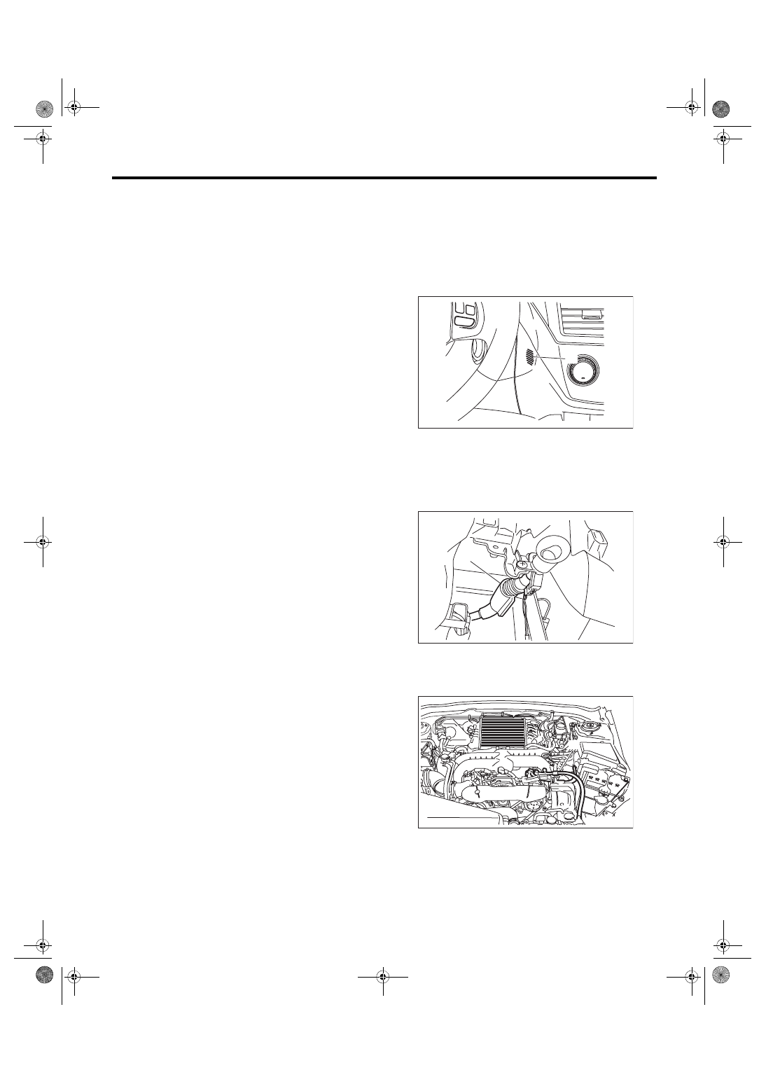
2. ASPIRATOR HOSE
1) Turn the ignition switch to ON, and press the A/C
switch.
2) Turn the temperature control dial to maximum
hot position.
3) Set the blow vents to the DEF position.
4) Turn the fan switch to “MAX” position.
5) Put a strip of paper close to the front side of in-
vehicle sensor suction port (A) located in the instru-
ment panel lower cover, and check that air is being
sucked into the port by seeing the paper moving to-
wards the port.
NOTE:
Be careful not to let the paper get sucked into the
port.
6) If the paper does not move at all, remove the in-
strument panel lower cover <Ref. to EI-49, RE-
MOVAL, Instrument Panel Lower Cover.> and
check for poor connection of the aspirator hose (A),
in-vehicle sensor and heater unit, and repair them if
3. A/C LINE
Check the connection for A/C line (A) and lower
side high-pressure pipe.
4. CONTROL LINKAGE
1) Check the state of mode door linkage.
2) Check the state of air mix door linkage.
3) Check the state of intake door linkage.
AC-01714
(A)
AC-02460
(A)
AC-01878
(A)
(A)
(A)
AC(diag)-4
General Description
HVAC SYSTEM (AUTO A/C) (DIAGNOSTICS)
5. CONTROL SWITCHES
Start the engine and warm up completely.
1) Inspection using switches
2) Inspection of compressor operation
3) Inspection of illumination control
No.
Point to check
Switch operation
Judgment standard
1
Air flow control dial
Turn the dial to the right.
Outlet opening (mode) switches AUTO →
VENT → BI-LEVEL → HEAT → DEF/HEAT →
DEF each time turning the dial.
2
Fan speed control dial Turn the dial to the right.
Each time the dial is turned, the fan speed
switches OFF → AUTO → 1st → 2nd → 3rd →
4th → 5th → 6th → 7th.
3
FRESH/RECIRC
switch
Press the FRESH/RECIRC switch.
Inlet opening switches RECIRC → FRESH →
RECIRC each time pressing the switch. (LED
illuminates at RECIRC)
Set the air flow control dial and fan speed control
dial to the AUTO position.
The system switches to AUTO.
4
A/C switch
Turn the A/C switch to ON with the fan speed con-
trol dial set to other than OFF position.
The LED lights and the compressor operates.
Set the air flow control dial and fan speed control
dial to the AUTO position.
The system switches to AUTO.
5
Auto function
Operate in order from
1).
1) Set the following dial to AUTO.
• Air flow control dial
• Fan speed control dial
2) Turn the temperature control dial completely to
the left, and set to the maximum cool position.
• Outlet air temperature: COOL
• Fan speed: Max.
• Outlet opening: VENT
• Inlet opening: RECIRC
• Compressor: AUTO
3) Turn the temperature control dial to the right
slowly up to the maximum hot position.
• Outlet air temperature: COOL → HOT
• Fan speed: AUTO
• Outlet opening: AUTO
• Inlet opening: AUTO
• Compressor: AUTO
4) Turn the temperature control dial fully to the
right, to the maximum hot position.
• Outlet air temperature: HOT
• Fan speed: Max.
• Outlet opening: HEAT
• Inlet opening: FRESH
• Compressor: AUTO
6
Defroster Interlock
Function
Set the air flow control dial to the DEF or the DEF/
HEAT position.
• Outlet air temperature: AUTO
• Fan speed: AUTO
• Outlet opening: DEF or DEF/HEAT
• Inlet opening: FRESH
• Compressor: ON
7
Rear defogger switch
Press the rear defogger switch.
LED illuminates.
No.
Point to check
Switch operation
Judgment standard
1
Compressor
1) Turn the A/C switch to ON.
2) Set the FAN switch between LO and HI.
Compressor: ON
No.
Point to check
Switch operation
Judgment standard
1
Illumination
Turn the lighting switch to ON.
Illumination comes on.
If the LED lights, the LED will dim.
Нет комментариевНе стесняйтесь поделиться с нами вашим ценным мнением.
Текст