Subaru Impreza 3 / Impreza WRX / Impreza WRX STI. Service manual — part 712
SE-17
Seat Heater System
SEATS
4. Seat Heater System
A: REMOVAL
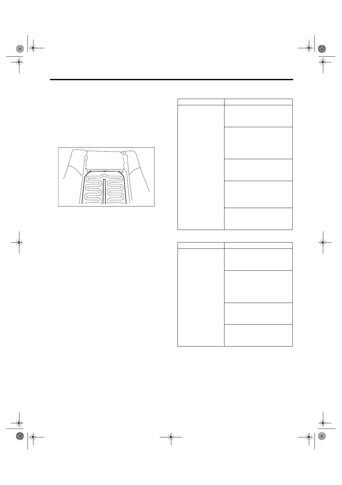
1. SEAT HEATER MODULE
1) Remove the front seats. <Ref. to SE-6, REMOV-
2) Remove the backrest cover of front seat and
seat cushion cover. <Ref. to SE-6, DISASSEM-
3) Remove the seat heater module.
2. SEAT HEATER SWITCH
1) Remove the console box. <Ref. to EI-51, RE-
2) Remove the seat heater switch from the console
box.
B: INSTALLATION
Install each part in the reverse order of removal.
C: INSPECTION
1. WIRING DIAGRAM
Refer to “Seat Heater System” in the wiring dia-
gram. <Ref. to WI-88, WIRING DIAGRAM, Seat
2. DIAGNOSTIC CHART
• Models with SI-DRIVE
• Models without SI-DRIVE
3. CHECK SEAT HEATER FUSE
Remove the seat heater fuse, and then visually
check.
Is the fuse blown out?
• Yes → Replace the fuse.
• No → Check the power supply and ground cir-
cuit.
SE-00082
Symptoms
Repair order
Seat heater does not
operate.
1. Check the fuse. <Ref. to SE-17,
2. Check the seat heater system
power supply and ground circuit.
3. Check the thermistor circuit.
4. Check the seat heater switch
circuit. <Ref. to SE-18, CHECK
5. Check the seat heater module.
Symptoms
Repair order
Seat heater does not
operate.
1. Check the fuse. <Ref. to SE-17,
2. Check the seat heater system
power supply and ground circuit.
3. Check the seat heater switch
circuit. <Ref. to SE-19, SEAT
HEATER SWITCH, INSPEC-
TION, Seat Heater System.>
SE-18
Seat Heater System
SEATS
4. CHECK POWER SUPPLY AND GROUND
CIRCUIT
1) CHECK POWER SUPPLY CIRCUIT.
(1) Disconnect the connector of seat heater
switch.
(2) Turn the ignition switch to ON.
(3) Measure the voltage between harness con-
nector terminal and chassis ground.
Connector & terminal
(AD8) No. 12 (+) — Chassis ground (–):
Is the voltage 12 V or more?
• Yes → Go to symptom 2.
• No → Check the harness between the seat
heater switch and fuse.
2) Check ground circuit
Measure the resistance between harness connec-
tor terminal and chassis ground.
Connector & terminal
(AD8) No. 2 — Chassis ground:
Is the resistance less than 10 Ω?
• Yes → Go to symptom 3.
• No → Repair the harness.
3) Check ground circuit
Measure the resistance between seat heater
switch terminals.
Connector & terminal
(AD8) No. 1 — (AD8) No. 2:
(AD8) No. 3 — (AD8) No. 2:
Is the resistance less than 10 Ω?
• Yes → The power supply and ground circuit are
normal.
• No → Replace the seat heater switch.
5. CHECK THERMISTOR CIRCUIT
Measure the resistance between harness connec-
tor terminals.
Connector & terminal
Check LHD side
(AD8) No. 8 — (AD8) No. 3:
Check RHD side
(AD8) No. 6 — (AD8) No. 1:
Is the resistance between 1 kΩ and 200 kΩ?
• Yes → Thermistor circuit is normal
• No → Harness faulty or thermistor faulty
6. CHECK SEAT HEATER SWITCH
1) Check thermistor output voltage.
(1) Connect the seat heater switch connector.
(2) Turn the ignition switch to ON.
(3) Measure the voltage between the seat heat-
er switch and chassis ground.
Connector & terminal:
LHD side seat
(AD8) No. 8 (+) — Chassis ground (–):
RHD side seat
(AD8) No. 6 (+) — Chassis ground (–):
Is the voltage 1.5 V or more?
• Yes → Go to symptom 2.
• No → Replace the seat heater switch.
2) Check output voltage.
(1) Turn the ignition switch to ON.
(2) Measure the voltage between the seat heat-
er switch and chassis ground when turning the
switch to a position other than OFF.
Connector & terminal:
LHD side seat
(AD8) No. 9 (+) — Chassis ground (–):
RHD side seat
(AD8) No. 7 (+) — Chassis ground (–):
Does the voltage repeat 12 V ←→ 0 V?
• Yes → The harness or thermistor is faulty, or
the heater has an open circuit.
• No → Replace the seat heater switch.
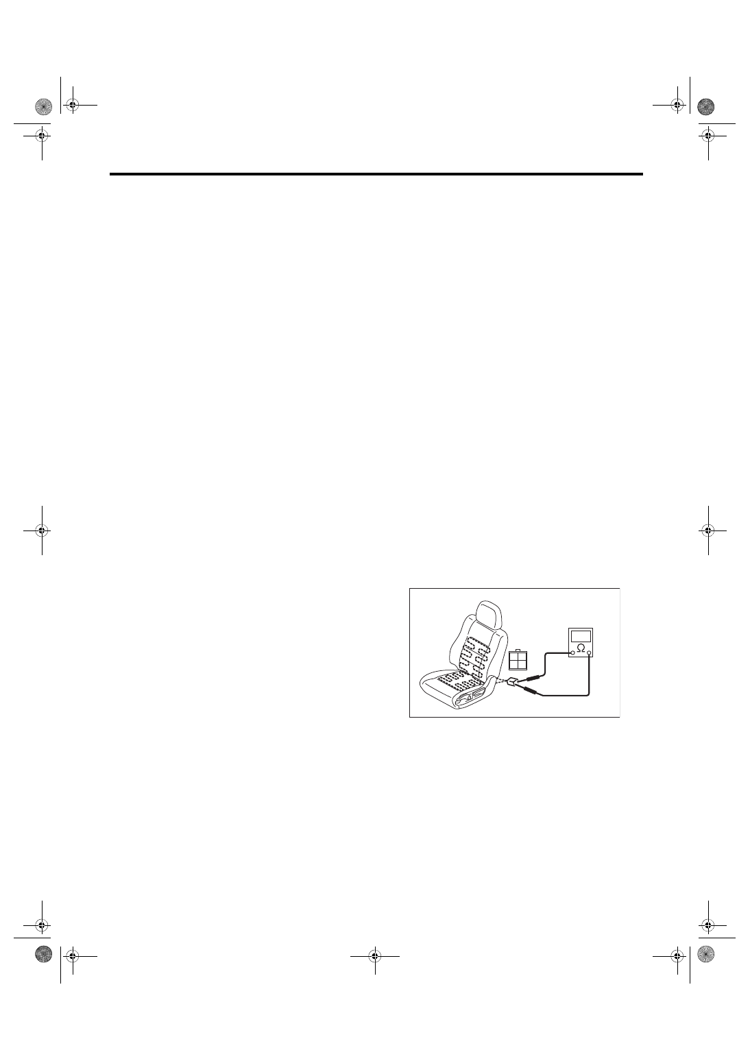
7. CHECK SEAT HEATER MODULE
1) Disconnect the seat heater module connector,
and check the continuity between terminals of con-
nector.
Connector & terminal
No. 1 — No. 3:
No. 1 — No. 4:
No. 3 — No. 4:
Is there continuity between connector terminals?
•
Continuity exists. →
Seat heater module is normal. If there is a malfunc-
tion, check the seat heater switch and vehicle body
side harness.
•
Continuity does not exist. →
No. 1 — No. 3: → Go to step 2).
No. 1 — No. 4: → Go to step 2).
No. 3 — No. 4: → Replace the seat heater mod-
ule of seat cushion side.
SE-00765
1
2
3
4
SE-19
Seat Heater System
SEATS
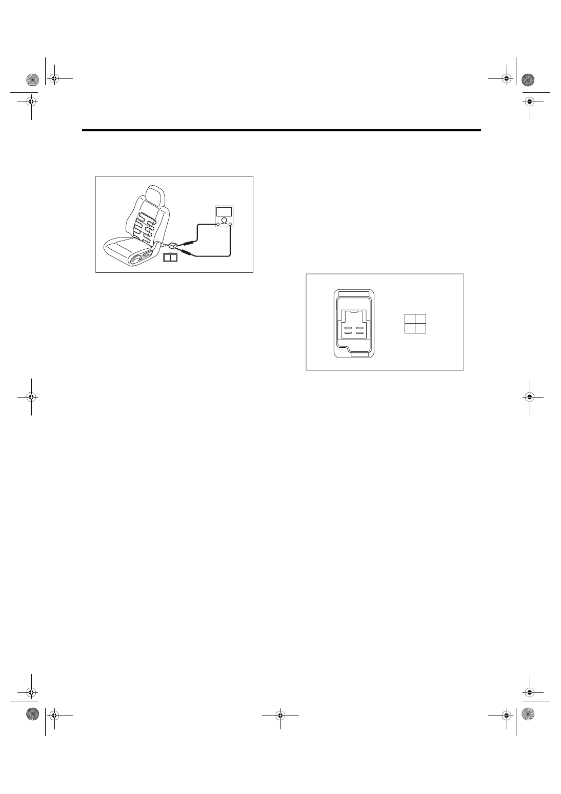
2) Disconnect the seat heater module of backrest
side, and check the continuity between connector
terminals of the seat heater module unit of backrest
side.
Is there continuity between connector terminals?
•
Continuity exists. →
Replace the seat heater module of seat cushion
side.
•
Continuity does not exist. →
Replace the seat heater module of backrest side.
8. CHECK POWER SUPPLY AND GROUND
CIRCUIT
1) Check power supply circuit.
(1) Disconnect the connector of seat heater
switch.
(2) Turn the ignition switch to ON.
(3) Measure the voltage between harness con-
nector terminal and chassis ground.
Connector & terminal
(R42) No. 2 (+) — Chassis ground (–):
(R43) No. 2 (+) — Chassis ground (–):
Is the voltage 12 V or more?
• Yes → Go to symptom 2.
• No → Check the harness between the seat
heater switch and fuse.
2) Check ground circuit.
Measure the resistance between harness connec-
tor terminal and chassis ground.
Connector & terminal
(R42) No. 3 — Chassis ground:
(R43) No. 3 — Chassis ground:
Is the resistance less than 10 Ω?
• Yes → Go to symptom 3.
• No → Repair the harness.
3) Check ground circuit.
Measure the resistance between seat heater
switch terminals.
Connector & terminal
(R42) No. 2 — (R42) No. 3:
(R43) No. 2 — (R43) No. 3:
Is the resistance less than 10 Ω?
• Yes → The power supply and ground circuit are
normal.
• No → Replace the seat heater switch.
9. SEAT HEATER SWITCH
1) Inspect the continuity between the seat heater
switch terminals.
Connector & terminal
HI
No. 2 — No. 1:
No. 2 — No. 3:
No. 1 — No. 3:
No. 4 — No. 3:
LOW
No. 2 — No. 4:
No. 2 — No. 3:
No. 4 — No. 3:
2) If no continuity exists, replace the seat heater
switch with a new part.
SE-01206
1
2
SE-00857
1
2
3
4
SE-20
Seat Heater System
SEATS
Нет комментариевНе стесняйтесь поделиться с нами вашим ценным мнением.
Текст