Subaru Impreza 3 / Impreza WRX / Impreza WRX STI. Service manual — part 224
EN(H4DOTC)(diag)-120
Diagnostic Procedure with Diagnostic Trouble Code (DTC)
ENGINE (DIAGNOSTICS)
O: DTC P0101 MASS OR VOLUME AIR FLOW CIRCUIT RANGE/PERFOR-
MANCE
DTC DETECTING CONDITION:
• Detected when two consecutive driving cycles with fault occur.
• GENERAL DESCRIPTION <Ref. to GD(H4DOTC)-34, DTC P0101 MASS OR VOLUME AIR FLOW CIR-
CUIT RANGE/PERFORMANCE, Diagnostic Trouble Code (DTC) Detecting Criteria.>
TROUBLE SYMPTOM:
• Improper idling
• Engine stalls.
• Poor driving performance
CAUTION:
After servicing or replacing faulty parts, perform Clear Memory Mode <Ref. to EN(H4DOTC)(diag)-63,
OPERATION, Clear Memory Mode.>, and Inspection Mode <Ref. to EN(H4DOTC)(diag)-49, PROCE-
Step
Check
Yes
No
1
CHECK FOR ANY OTHER DTC ON DISPLAY. Is any other DTC displayed?
EN(H4DOTC)(diag)-121
Diagnostic Procedure with Diagnostic Trouble Code (DTC)
ENGINE (DIAGNOSTICS)
P: DTC P0102 MASS OR VOLUME AIR FLOW CIRCUIT LOW INPUT
DTC DETECTING CONDITION:
• Immediately at fault recognition
• GENERAL DESCRIPTION <Ref. to GD(H4DOTC)-36, DTC P0102 MASS OR VOLUME AIR FLOW CIR-
CUIT LOW INPUT, Diagnostic Trouble Code (DTC) Detecting Criteria.>
TROUBLE SYMPTOM:
• Improper idling
• Engine stalls.
• Poor driving performance
CAUTION:
After servicing or replacing faulty parts, perform Clear Memory Mode <Ref. to EN(H4DOTC)(diag)-63,
OPERATION, Clear Memory Mode.>, and Inspection Mode <Ref. to EN(H4DOTC)(diag)-49, PROCE-
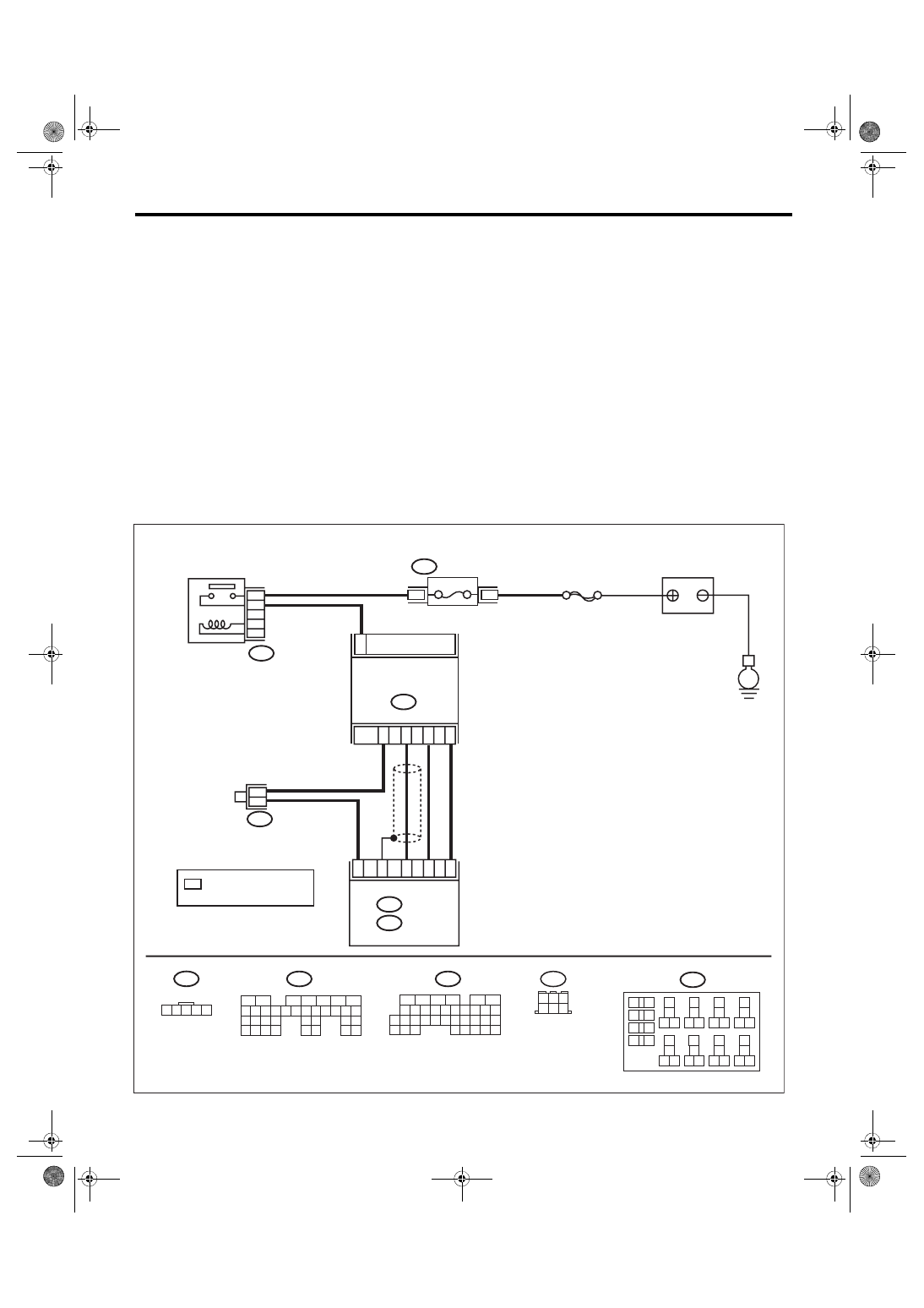
WIRING DIAGRAM:
• Engine electrical system, without SI-DRIVE <Ref. to WI-32, WITHOUT SI-DRIVE, WIRING DIAGRAM,
• Engine electrical system, with SI-DRIVE <Ref. to WI-48, WITH SI-DRIVE, WIRING DIAGRAM, Engine
ECM
EN-08725
B135
B:
B3
B83
3
B3
B135
B:
B136
C:
1 2 3 4 5
*
*
4
1
5
2
C11
C31
C22
B30
C10
*
B220
24
23
22
21
15A
B220
3
4
B136
C:
B83
6
4 5
3
2
1
35
27
16
10 11 12 13 14 15
25
24
30
9
8
7
17 18 19 20
28
21 22 23
29
32
31
1
2
3
4
5
6
26
33 34
B220
18
19
6
7
4
3
5
2
1
12
11
10
9
8
40
36 39
38
37
34
33
35
32
28 31
30
29
23
22
21
20
26
25
24
27
17
16
15
14
13
35
34
33
32
31
30
29
21
20
19
18
17
16
28
27
26
15
14
13
12
11
25
23
22
24
10
3
4
9
1
2
8
7
6
5
SBF-7
E
FUSE
(RELAY BLOCK)
MAIN RELAY
: TERMINAL No. OPTIONAL
ARRANGEMENT
MASS AIR FLOW &
INTAKE AIR
TEMPERATURE SENSOR
BATTERY
EN(H4DOTC)(diag)-122
Diagnostic Procedure with Diagnostic Trouble Code (DTC)
ENGINE (DIAGNOSTICS)
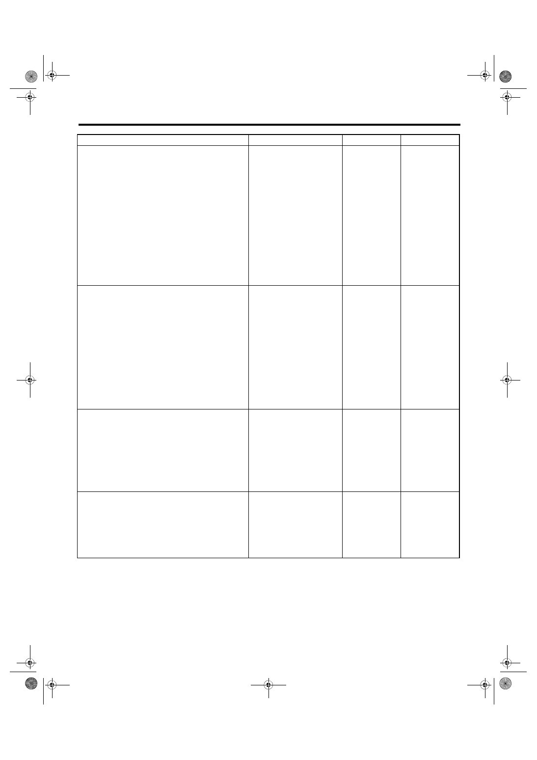
Step
Check
Yes
No
1
CHECK CURRENT DATA.
1) Start the engine.
2) Read the value of «Air Flow Sensor Volt-
age» using Subaru Select Monitor.
NOTE:
Is the value of «Air Flow Sensor
Voltage» less than 0.2 V?
Even if DTC is
detected, the cir-
cuit has returned to
a normal condition
at this time. Repro-
duce the failure,
and then perform
the diagnosis
again.
NOTE:
In this case, tem-
porary poor con-
tact of connector,
temporary open or
short circuit of har-
ness may be the
cause.
2
CHECK POWER SUPPLY OF MASS AIR
FLOW AND INTAKE AIR TEMPERATURE
SENSOR.
1) Turn the ignition switch to OFF.
2) Disconnect the connectors from the mass
air flow and intake air temperature sensor.
3) Turn the ignition switch to ON.
4) Measure the voltage between mass air flow
and intake air temperature sensor connector
and engine ground.
Connector & terminal
(B3) No. 3 (+) — Engine ground (–):
Is the voltage 10 V or more?
Repair the harness
and connector.
NOTE:
In this case, repair
the following item:
• Open circuit in
harness between
main relay connec-
tor and mass air
flow and intake air
temperature sen-
sor connector
• Poor contact of
main relay connec-
tor
3
CHECK HARNESS BETWEEN ECM AND
MASS AIR FLOW AND INTAKE AIR TEM-
PERATURE SENSOR CONNECTOR.
1) Turn the ignition switch to OFF.
2) Disconnect the connector from ECM.
3) Measure the resistance of harness between
ECM connector and the mass air flow and
intake air temperature sensor connector.
Connector & terminal
(B136) No. 22 — (B3) No. 5:
Is the resistance less than 1 Ω? Go to step
Repair the open
circuit of harness
between ECM con-
nector and the
mass air flow and
intake air tempera-
ture sensor con-
nector.
4
CHECK HARNESS BETWEEN ECM AND
MASS AIR FLOW AND INTAKE AIR TEM-
PERATURE SENSOR CONNECTOR.
Measure the resistance between ECM connec-
tor and chassis ground.
Connector & terminal
(B136) No. 22 — Chassis ground:
Is the resistance 1 MΩ or
more?
Repair the ground
short circuit of har-
ness between
ECM connector
and the mass air
flow and intake air
temperature sen-
sor connector.
EN(H4DOTC)(diag)-123
Diagnostic Procedure with Diagnostic Trouble Code (DTC)
ENGINE (DIAGNOSTICS)
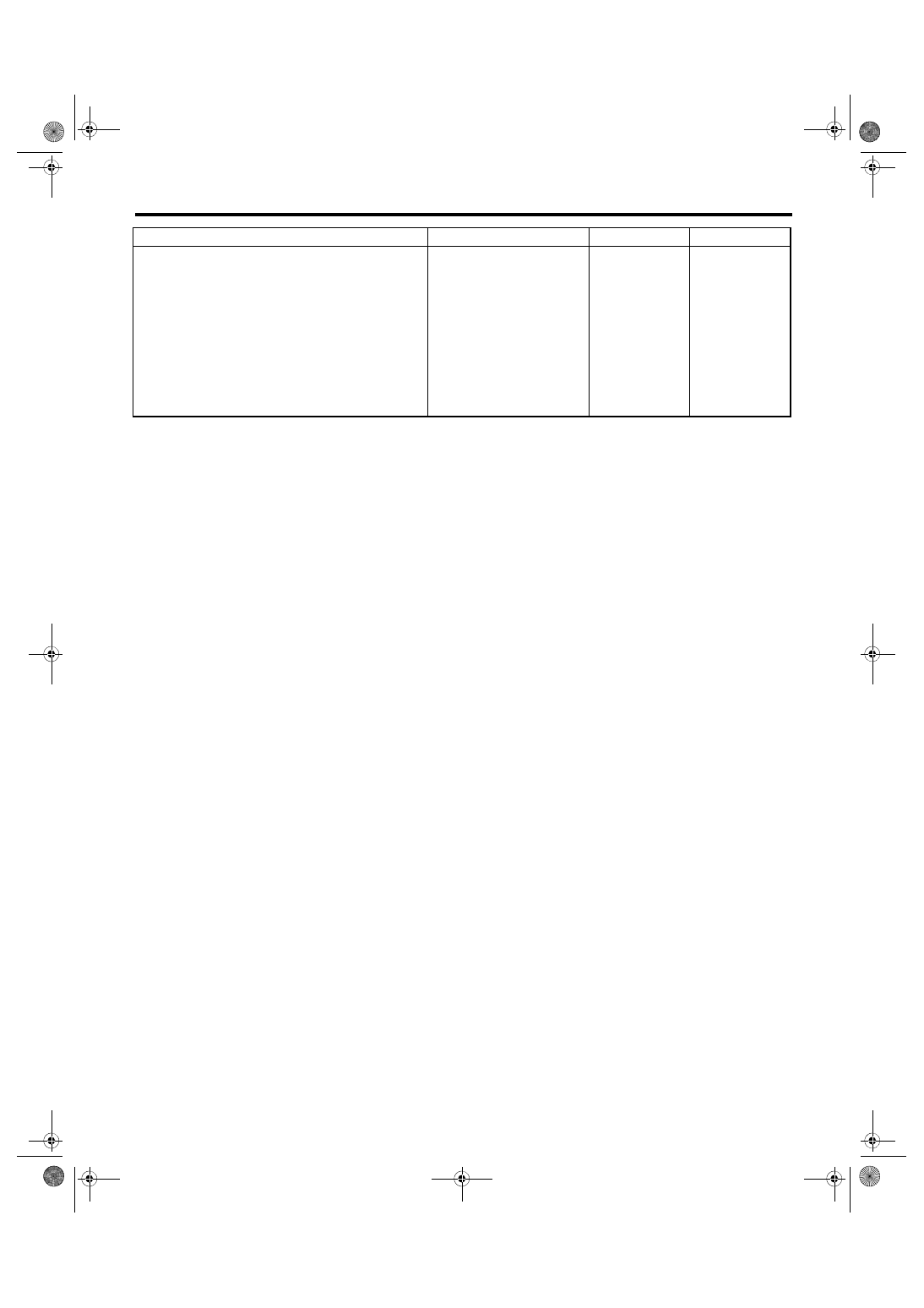
5
CHECK FOR POOR CONTACT.
Check for poor contact of ECM and mass air
flow and intake air temperature sensor connec-
tor.
Is there poor contact of ECM or
mass air flow and intake air
temperature sensor connector?
Repair the poor
contact of ECM or
mass air flow and
intake air tempera-
ture sensor con-
nector.
Step
Check
Yes
No
Нет комментариевНе стесняйтесь поделиться с нами вашим ценным мнением.
Текст