Subaru Impreza 3 / Impreza WRX / Impreza WRX STI. Service manual — part 222
EN(H4DOTC)(diag)-112
Diagnostic Procedure with Diagnostic Trouble Code (DTC)
ENGINE (DIAGNOSTICS)
2
CHECK GROUND CIRCUIT FOR ECM.
1) Disconnect the connector from ECM.
2) Measure the resistance between ECM con-
nector and chassis ground.
Connector & terminal
(B134) No. 3 — Chassis ground:
(B134) No. 4 — Chassis ground:
(B134) No. 6 — Chassis ground:
(B137) No. 1 — Chassis ground:
(B137) No. 3 — Chassis ground:
Is the resistance less than 5 Ω? Repair the poor
contact of ECM
connector.
Repair the harness
and connector.
NOTE:
In this case, repair
the following item:
• Open circuit of
harness between
ECM
connector
and engine ground
• Poor contact of
coupling connector
Step
Check
Yes
No
EN(H4DOTC)(diag)-113
Diagnostic Procedure with Diagnostic Trouble Code (DTC)
ENGINE (DIAGNOSTICS)
L: DTC P0037 HO2S HEATER CONTROL CIRCUIT LOW (BANK 1 SENSOR 2)
DTC DETECTING CONDITION:
• Detected when 2 consecutive driving cycles with fault occur.
• GENERAL DESCRIPTION <Ref. to GD(H4DOTC)-28, DTC P0037 HO2S HEATER CONTROL CIRCUIT
LOW (BANK 1 SENSOR 2), Diagnostic Trouble Code (DTC) Detecting Criteria.>
CAUTION:
After servicing or replacing faulty parts, perform Clear Memory Mode <Ref. to EN(H4DOTC)(diag)-63,
OPERATION, Clear Memory Mode.>, and Inspection Mode <Ref. to EN(H4DOTC)(diag)-49, PROCE-
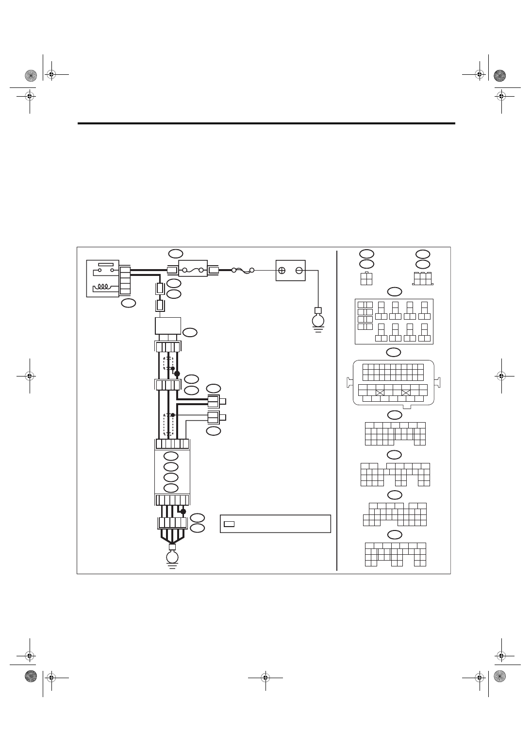
WIRING DIAGRAM:
• Models without SI-DRIVE <Ref. to WI-32, WITHOUT SI-DRIVE, WIRING DIAGRAM, Engine Electrical
ECM
6
4 5
3
2
1
*
2
1
B220
15A
9
10
11
12
B220
*
*
1 2
3 4
D1
36
A4
40
34
35
B21
E2
D3
A6
A3
B220
13
14
15 16
17
27
24
25
26
20
21
22
23
29
30
31
28
32 35
33
34
37
38
39
36
40
8
9
10
11 12
1
2
5
3
4
7
6
19
18
B134
5
6
7
8
2
1
9
4
3
10
24
22 23
25
11 12 13 14 15
26 27
28
16 17
18 19 20 21
33 34
29
32
30 31
A:
D: B137
C: B136
B: B135
A:
T6
B134
C9
B30
C20
B6
*
*
B21
1 2 3 4
12 13 14 15
5 6 7 8
16 17 18 19
9 10 11
20 21 22
23 24 25 26 27 28 29 30 31 32 33
35
34
37
36
39
38
41
40
43
42
44 45
47
46
49
48
51
50
53
52
54
4
1
3
4
1
3
B19
T5
22
T5
B19
5
6
7
8
2
1
9
4
3
10
22 23
11 12 13 14 15
24 25
26
16 17
18 19 20 21
27
28 29
30 31
B135
B:
5
6
7
8
2
1
9
4
3
10
24
22 23
25
11 12 13 14 15
26 27
28
16 17 18 19
20 21
29 30 31
32 33
34 35
B136
C:
5
6
7 8
2
1
9
4
3
10
24
22 23
25
11 12 13 14 15
26 27
28
16
17 18 19 20 21
33 34
29
32
30
31
35
D: B137
B19
T6
B83
B138
B138
B83
EN-08722
E
E
SBF-5
BATTERY
: TERMINAL No. OPTIONAL ARRANGEMENT
REAR
OXYGEN SENSOR
A/F, OXYGEN SENSOR
RELAY
FUSE
(RELAY BLOCK)
EN(H4DOTC)(diag)-114
Diagnostic Procedure with Diagnostic Trouble Code (DTC)
ENGINE (DIAGNOSTICS)
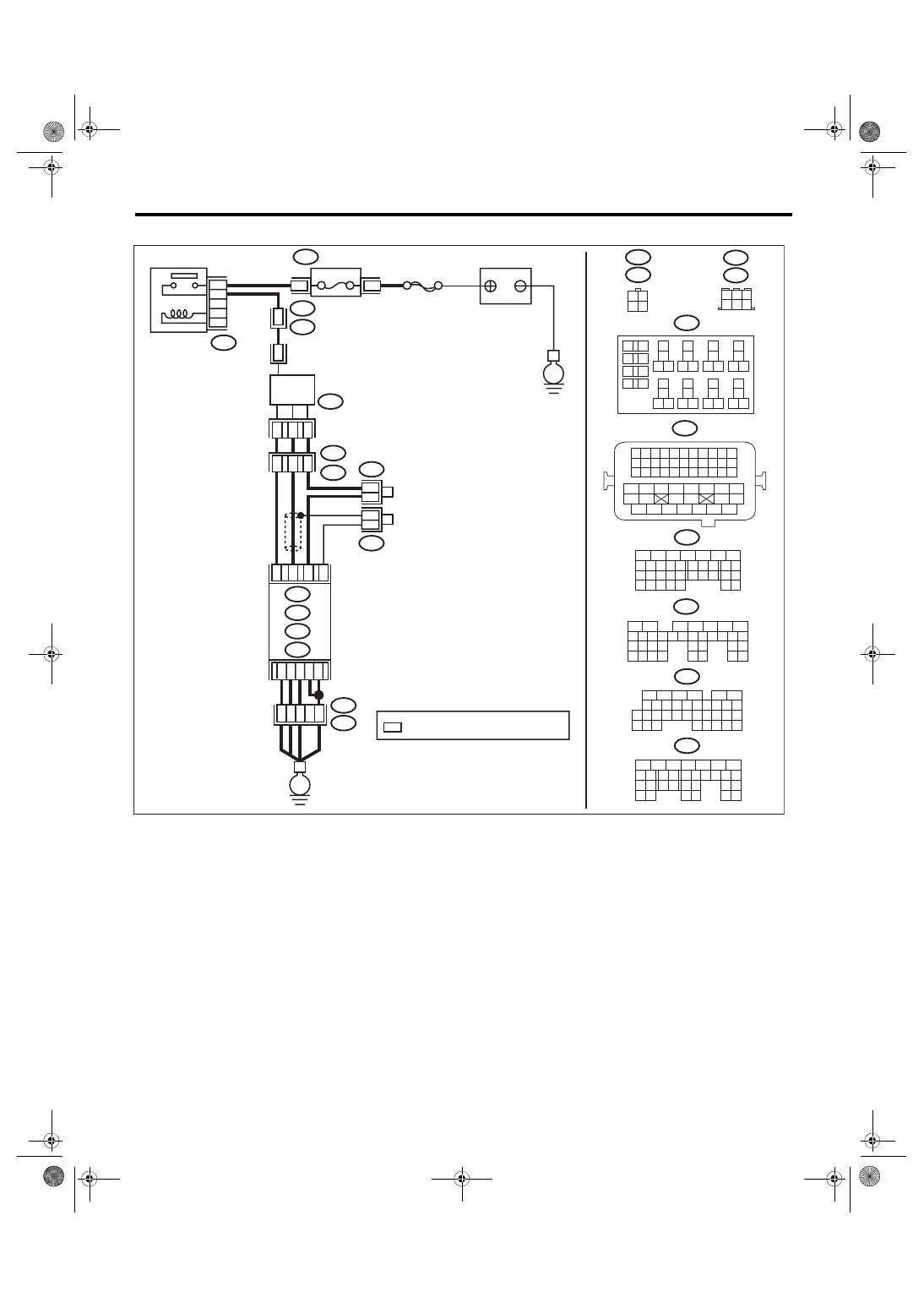
• Models with SI-DRIVE <Ref. to WI-48, WITH SI-DRIVE, WIRING DIAGRAM, Engine Electrical System.>
ECM
6
4 5
3
2
1
*
2
1
B220
15A
9
10
11
12
B220
*
*
1 2
3 4
D1
36
D3 A4
40
34
35
B21
E2
A6
A3
B220
13
14
15 16
17
27
24
25
26
20
21
22
23
29
30
31
28
32 35
33
34
37
38
39
36
40
8
9
10
11 12
1
2
5
3
4
7
6
19
18
B134
5
6
7
8
2
1
9
4
3
10
24
22 23
25
11 12 13 14 15
26 27
28
16 17
18 19 20 21
33 34
29
32
30 31
A:
D: B137
C: B136
B: B135
A:
T6
B134
C9
B30
C20
B6
*
*
B21
1 2 3 4
12 13 14 15
5 6 7 8
16 17 18 19
9 10 11
20 21 22
23 24 25 26 27 28 29 30 31 32 33
35
34
37
36
39
38
41
40
43
42
44 45
47
46
49
48
51
50
53
52
54
4
1
3
4
1
3
B19
T5
22
T5
B19
5
6
7
8
2
1
9
4
3
10
22 23
11 12 13 14 15
24 25
26
16 17
18 19 20 21
27
28 29
30 31
B135
B:
5
6
7
8
2
1
9
4
3
10
24
22 23
25
11 12 13 14 15
26 27
28
16 17 18 19
20 21
29 30 31
32 33
34 35
B136
C:
5
6
7 8
2
1
9
4
3
10
24
22 23
25
11 12 13 14 15
26 27
28
16
17 18 19 20 21
33 34
29
32
30
31
35
D: B137
B19
T6
B83
B138
B138
B83
EN-08723
SBF-5
E
E
BATTERY
: TERMINAL No. OPTIONAL ARRANGEMENT
REAR
OXYGEN SENSOR
A/F, OXYGEN SENSOR
RELAY
FUSE
(RELAY BLOCK)
EN(H4DOTC)(diag)-115
Diagnostic Procedure with Diagnostic Trouble Code (DTC)
ENGINE (DIAGNOSTICS)
Step
Check
Yes
No
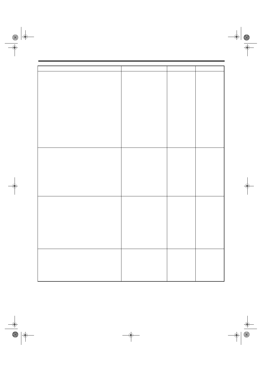
1
CHECK POWER SUPPLY TO REAR OXY-
GEN SENSOR.
1) Turn the ignition switch to OFF.
2) Disconnect the connector from rear oxygen
sensor.
3) Turn the ignition switch to ON.
4) Measure the voltage between rear oxygen
sensor connector and engine ground.
Connector & terminal
(T6) No. 2 (+) — Engine ground (–):
Is the voltage 10 V or more?
Repair the power
supply line.
NOTE:
In this case, repair
the following item:
• Open circuit in
harness between
A/F, oxygen sen-
sor relay and rear
oxygen
sensor
connector
• Poor contact of
A/F, oxygen sen-
sor relay connector
• Poor contact of
coupling connector
• Malfunction of A/
F, oxygen sensor
relay
2
CHECK HARNESS BETWEEN ECM AND
REAR OXYGEN SENSOR CONNECTOR.
1) Turn the ignition switch to OFF.
2) Disconnect the connector from ECM.
3) Measure the resistance between ECM con-
nector and rear oxygen sensor connector.
Connector & terminal
(B135) No. 6 — (T6) No. 1:
Is the resistance less than 1 Ω? Go to step
Repair the harness
and connector.
NOTE:
In this case, repair
the following item:
• Open circuit in
harness between
ECM
connector
and rear oxygen
sensor connector
• Poor contact of
coupling connector
3
CHECK GROUND CIRCUIT FOR ECM.
Measure the resistance of harness between
ECM connector and chassis ground.
Connector & terminal
(B134) No. 3 — Chassis ground:
(B134) No. 4 — Chassis ground:
(B134) No. 6 — Chassis ground:
(B137) No. 1 — Chassis ground:
(B137) No. 3 — Chassis ground:
Is the resistance less than 5 Ω? Go to step
Repair the harness
and connector.
NOTE:
In this case, repair
the following item:
• Open circuit of
harness between
ECM
connector
and engine ground
• Poor contact of
ECM connector
• Poor contact of
coupling connector
4
CHECK REAR OXYGEN SENSOR.
Measure the resistance between rear oxygen
sensor terminals.
Terminals
No. 1 — No. 2:
Is the resistance 5 — 6.4 Ω?
Repair the poor
contact of ECM
connector.
Нет комментариевНе стесняйтесь поделиться с нами вашим ценным мнением.
Текст