Subaru Impreza 3 / Impreza WRX / Impreza WRX STI. Service manual — part 83
ME(STI)-94
Cylinder Block
MECHANICAL
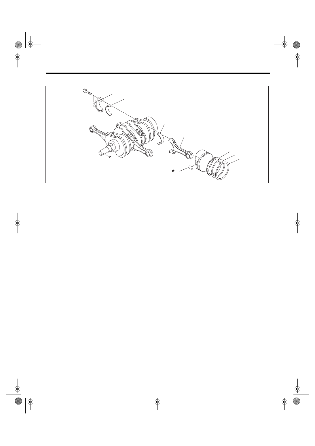
C: DISASSEMBLY
1) Remove the connecting rod cap.
2) Remove the connecting rod bearing.
NOTE:
Keep the removed connecting rods, connecting rod caps and bearings in order so that they are kept in their
original combinations/groups, and not mixed together.
3) Remove the piston rings using piston ring expander.
4) Remove the oil ring by hand.
NOTE:
Arrange the removed piston rings in proper order, to prevent confusion.
5) Remove the snap ring.
(1)
Top ring
(4)
Snap ring
(6)
Connecting rod bearing
(2)
Second ring
(5)
Connecting rod
(7)
Connecting rod cap
(3)
Oil ring
ME-04831
(6)
(6)
(4)
(3)
(2)
(1)
(7)
(5)
ME(STI)-95
Cylinder Block
MECHANICAL
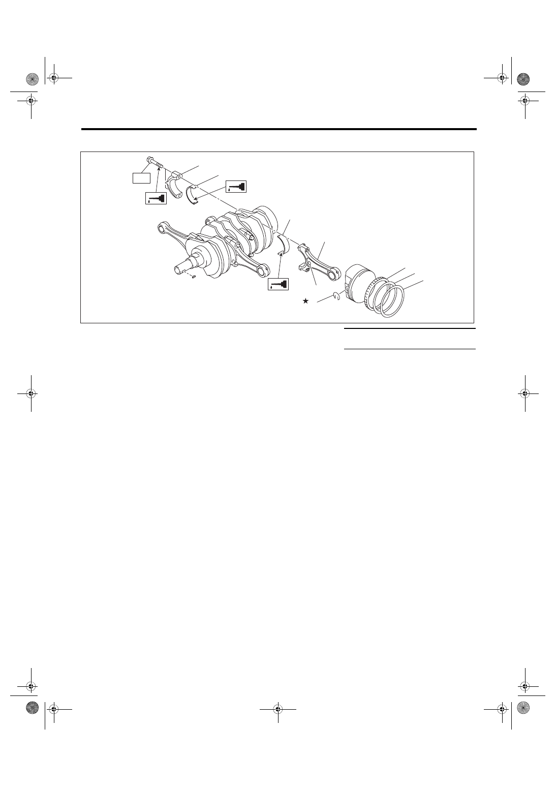
D: ASSEMBLY
1) Apply engine oil to the surface of the connecting rod bearings, and install the connecting rod bearings on
connecting rods and connecting rod caps.
2) Position each connecting rod with the side with a side mark facing forward, and install it.
3) Attach the connecting rod cap and tighten it with connecting rod bolt. Make sure the arrow on connecting
rod cap faces the front during installation.
NOTE:
• Each connecting rod has its own mating cap. Make sure that they are assembled correctly by checking
their matching number.
• When tightening the connecting rod bolts, apply oil on the threads.
Tightening torque:
52 N·m (5.3 kgf-m, 38.4 ft-lb)
4) Install the oil ring upper rail, expander and lower rail by hand.
5) Install the second ring and top ring using piston ring expander.
NOTE:
Assemble so that the piston ring mark “R” faces the top side of the piston.
(1)
Top ring
(5)
Side mark
Tightening torque: N·m (kgf-m, ft-lb)
(2)
Second ring
(6)
Connecting rod
T: 52 (5.3, 38.4)
(3)
Oil ring
(7)
Connecting rod bearing
(4)
Snap ring
(8)
Connecting rod cap
ME-04832
(7)
(7)
(4)
(3)
(2)
(1)
(8)
(6)
(5)
T
ME(STI)-96
Cylinder Block
MECHANICAL
E: INSPECTION
1. CYLINDER BLOCK
1) Check for cracks or damage. Use liquid pene-
trant tester on the important sections to check for
fissures. Check that there are no marks of gas leak-
ing or water leaking on gasket installing surface.
2) Check the oil passages for clogging.
3) Inspect the cylinder block surface that mates
with cylinder head for warping by using a straight
edge, and correct by grinding if necessary.
Warping limit:
0.025 mm (0.00098 in)
Grinding limit:
0.1 mm (0.004 in)
Standard height of cylinder block:
201.0 mm (7.91 in)
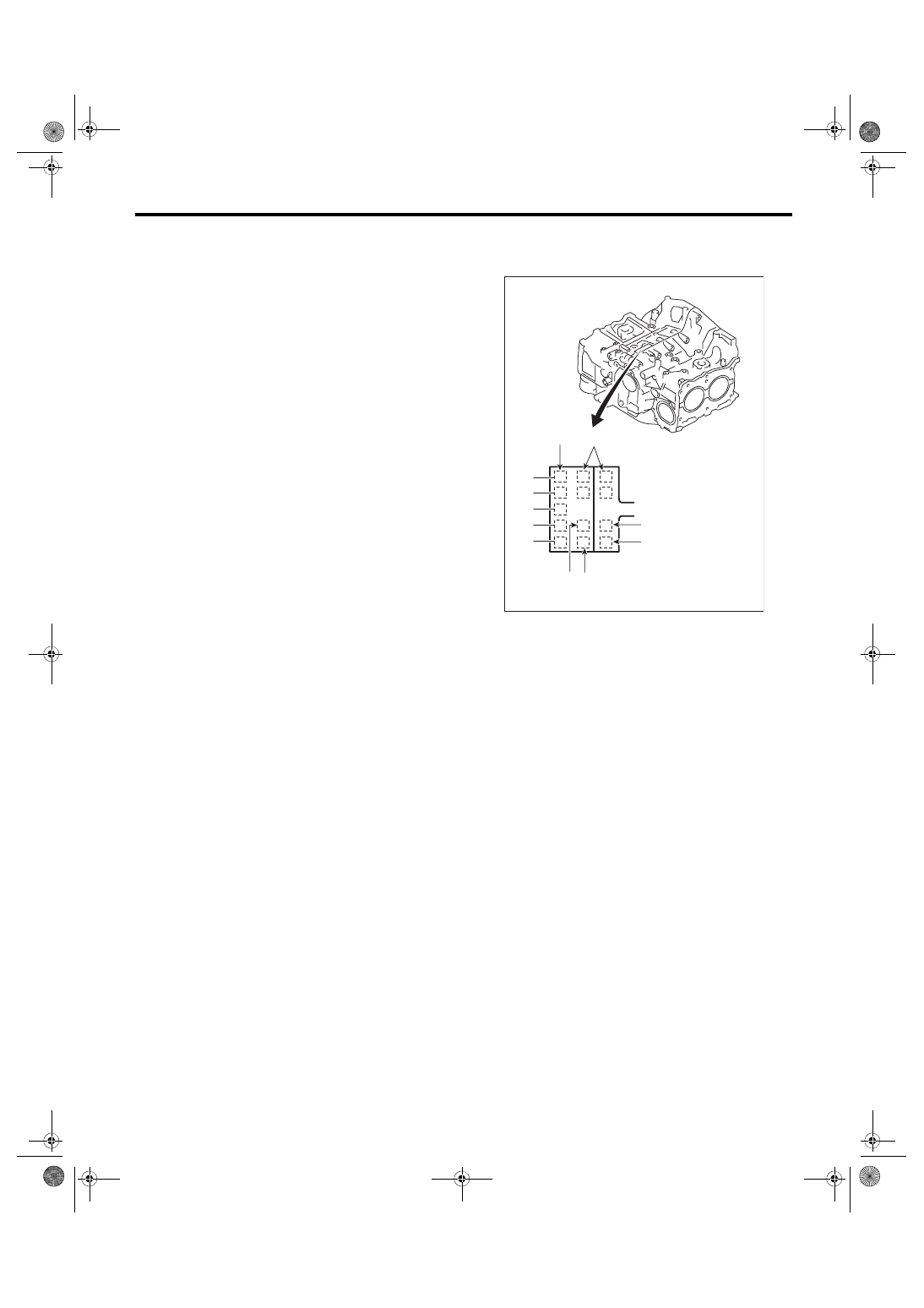
2. CYLINDER AND PISTON
1) The cylinder bore size is stamped on the front
upper face of the cylinder block.
NOTE:
• Measurement should be performed at a temper-
ature of 20°C (68°F).
• Standard sized pistons are classified into two
grades, “A” and “B”. These grades should be used
as guide lines in selecting a standard piston.
Standard diameter:
A: 99.505 — 99.515 mm (3.9175 — 3.9179 in)
B: 99.495 — 99.505 mm (3.9171 — 3.9175 in)
(A) Main journal size mark
(B) Cylinder block (RH) – (LH) combination mark
(C) #1 cylinder bore size mark
(D) #2 cylinder bore size mark
(E) #3 cylinder bore size mark
(F) #4 cylinder bore size mark
ME-00170
#5
#4
#3
#2
#1
(A)
(B)
(F)
(D)
A
B
A
B
5
4
5
4
(C)
(E)
ME(STI)-97
Cylinder Block
MECHANICAL
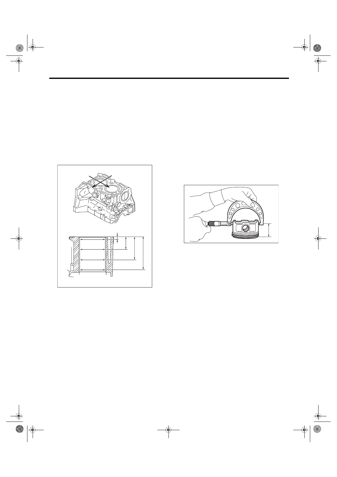
2) Measure inner diameter of each cylinder.
Measure the inner diameter of each cylinder in both
the thrust and piston pin directions at the heights as
shown in the figure, using a cylinder bore gauge.
NOTE:
Measurement should be performed at a tempera-
ture of 20°C (68°F).
Cylindricality:
Limit
0.015 mm (0.0006 in)
Out-of-roundness:
Limit
0.010 mm (0.0004 in)
3) When the piston is to be replaced due to general
or cylinder wear, select a suitable sized piston by
measuring the piston clearance.
4) Measure outer diameter of each piston.
Measure the outer diameter of each piston at the
height as shown in the figure. (Thrust direction)
NOTE:
Measurement should be performed at a tempera-
ture of 20°C (68°F).
Piston grade point H:
38.2 mm (1.50 in)
Piston outer diameter:
Standard
A: 99.505 — 99.515 mm (3.9175 — 3.9179 in)
B: 99.495 — 99.505 mm (3.9171 — 3.9175 in)
0.25 mm (0.0098 in) oversize
99.745 — 99.765 mm (3.9270 — 3.9278 in)
0.50 mm (0.0197 in) oversize
99.995 — 100.015 mm (3.9368 — 3.9376 in)
5) Calculate the clearance between cylinder and
piston.
NOTE:
Measurement should be performed at a tempera-
ture of 20°C (68°F).
Clearance between cylinder and piston at 20°C
(68°F):
Standard
–0.010 — 0.010 mm (–0.00039 — 0.00039 in)
6) Boring and honing
(1) If any of the measured value of cylindricality,
out-of-roundness or cylinder-to-piston clear-
ance is out of standard or if there is any damage
on the cylinder wall, rebore it to replace with an
oversize piston.
CAUTION:
When any of the cylinders needs reboring, all
other cylinders must be bored at the same time,
and replaced with oversize pistons.
(A) Piston pin direction
(B) Thrust direction
H1: 10 mm (0.39 in)
H2: 45 mm (1.77 in)
H3: 80 mm (3.15 in)
H4: 115 mm (4.53 in)
ME-04734
(A)
(B)
H2
H1
H3
H4
ME-00172
H
Нет комментариевНе стесняйтесь поделиться с нами вашим ценным мнением.
Текст