Subaru Impreza 3 / Impreza WRX / Impreza WRX STI. Service manual — part 82
ME(STI)-90
Cylinder Block
MECHANICAL
(7) Set the parts so that the #3 and #4 cylinders
are on the upper side. Following the same pro-
cedures as used for #1 and #2 cylinders, install
the pistons and piston pins.
(8) Install the service hole cover.
NOTE:
Use new O-rings.
Tightening torque:
6.4 N·m (0.7 kgf-m, 4.7 ft-lb)
22) Install the water tank pipe assembly onto the
cylinder block RH.
NOTE:
Use a new clamp for the water tank pipe assembly
clamp, fit the cut out in the ST with the protrusion on
the clamp as shown in the figure, and lock the
clamp.
ST 18353AA000 CLAMP PLIERS
23) Install the baffle plate.
Tightening torque:
6.4 N·m (0.7 kgf-m, 4.7 ft-lb)
24) Install the oil strainer.
NOTE:
Use new O-rings.
Tightening torque:
10 N·m (1.0 kgf-m, 7.4 ft-lb)
25) Tighten the oil strainer stay together with the
baffle plate.
Tightening torque:
6.4 N·m (0.7 kgf-m, 4.7 ft-lb)
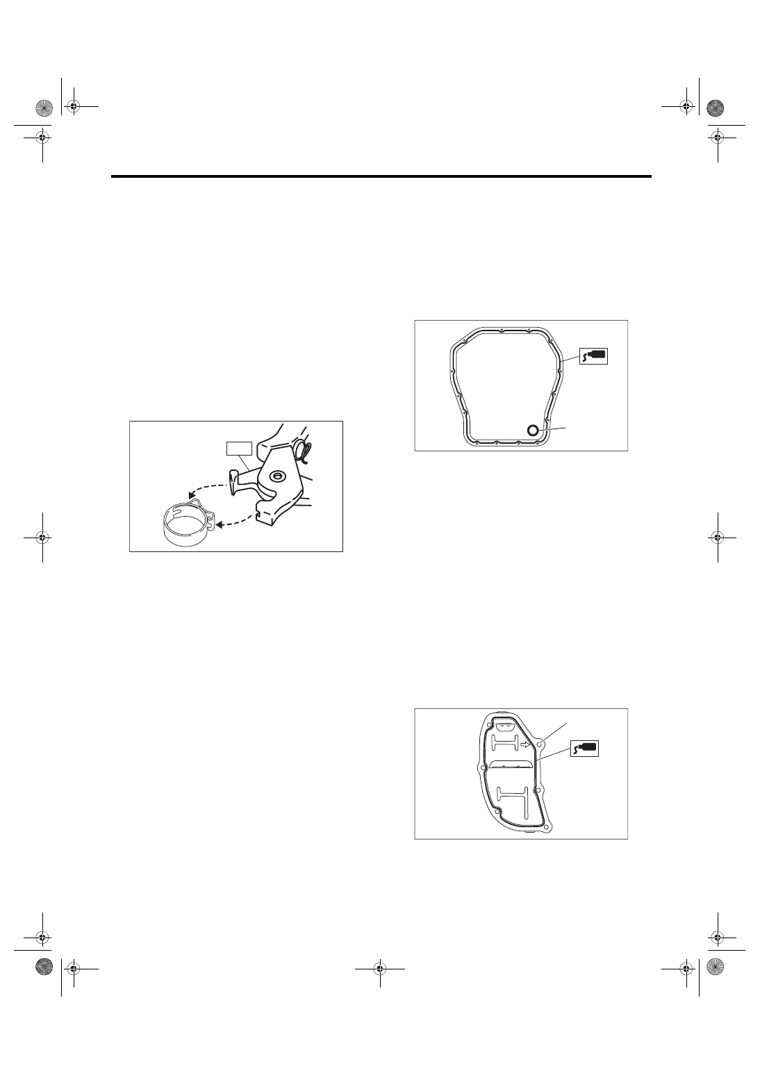
26) Apply liquid gasket to the mating surfaces of oil
pan, and install the oil pan.
NOTE:
Install within 5 min. after applying liquid gasket.
Liquid gasket:
THREE BOND 1217G (Part No. K0877Y0100)
or equivalent
Tightening torque:
5 N·m (0.5 kgf-m, 3.7 ft-lb)
27) Apply liquid gasket to the mating surface of oil
separator cover and the threaded portion of bolt (A)
shown in the figure (when reusing the bolt), and
then install the oil separator cover.
NOTE:
• Install within 5 min. after applying liquid gasket.
• Use new oil separator cover.
Liquid gasket:
Mating surface
THREE BOND 1217G (Part No.
K0877Y0100) or equivalent
Bolt thread (A) (when reusing the bolt)
THREE BOND 1324 (Part No. 004403042) or
equivalent
Tightening torque:
6.4 N·m (0.65 kgf-m, 4.7 ft-lb)
28) Install the flywheel. <Ref. to CL-14, INSTALLA-
29) Install the clutch disc and cover. <Ref. to CL-
11, INSTALLATION, Clutch Disc and Cover.>
ME-04374
ST
(A) Gasket
LU-02353
(A)
ME-03333
(A)
ME(STI)-91
Cylinder Block
MECHANICAL
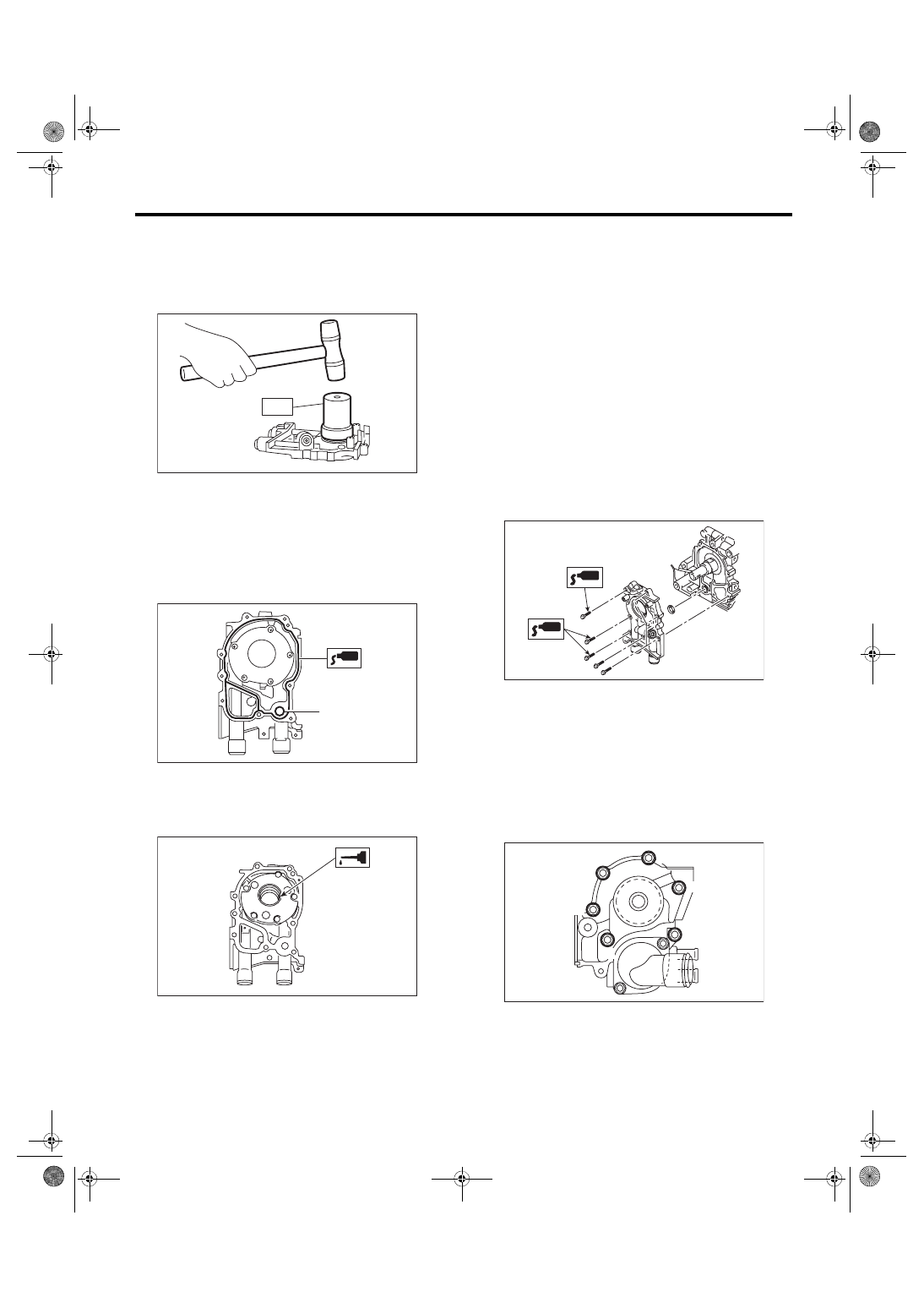
30) Install the oil pump.
(1) Using the ST, install the front oil seal.
ST 499587100
OIL SEAL INSTALLER
NOTE:
Use a new front oil seal.
(2) Apply liquid gasket to the mating surfaces of
oil pump.
NOTE:
Install within 5 min. after applying liquid gasket.
Liquid gasket:
THREE BOND 1217G (Part No. K0877Y0100)
or equivalent
(3) Apply a thin coat of engine oil to the inside of
front oil seal.
(4) Install the oil pump to cylinder block.
CAUTION:
• Be careful not to damage the front oil seal
during installation.
• Make sure the front oil seal lip is not folded.
NOTE:
• Align the flat surface of oil pump’s inner rotor with
that of crankshaft before installation.
• Use new O-rings.
• Do not forget to assemble O-rings.
(5) Apply liquid gasket to the three bolts thread
shown in figure. (when reusing bolts)
Liquid gasket:
THREE BOND 1324 (Part No. 004403042) or
equivalent
Tightening torque:
6.4 N·m (0.7 kgf-m, 4.7 ft-lb)
31) Install the water pump and gasket.
NOTE:
• When installing the water pump, tighten bolts in
two stages in alphabetical order as shown in the
figure.
• Use a new gasket.
Tightening torque:
First: 12 N·m (1.2 kgf-m, 8.9 ft-lb)
Second: 12 N·m (1.2 kgf-m, 8.9 ft-lb)
32) Install the water by-pass pipe for heater.
Tightening torque:
6.4 N·m (0.7 kgf-m, 4.7 ft-lb)
33) Install the oil cooler. <Ref. to LU(STI)-24, IN-
STALLATION, Engine Oil Cooler.>
(A) O-ring
LU-00021
ST
ME-00165
(A)
ME-00312
ME-04946
ME-04743
(F)
(C)
(A)
(E)
(D)
(B)
ME(STI)-92
Cylinder Block
MECHANICAL
34) Install the oil filter. <Ref. to LU(STI)-31, IN-
STALLATION, Engine Oil Filter.>
35) Install the cylinder head. <Ref. to ME(STI)-70,
36) Install the camshaft. <Ref. to ME(STI)-64, IN-
37) Install the generator and A/C compressor with
their brackets.
Tightening torque:
36 N·m (3.7 kgf-m, 26.6 ft-lb)
38) Install the crank sprocket. <Ref. to ME(STI)-60,
INSTALLATION, Crank Sprocket.>
39) Install the cam sprocket. <Ref. to ME(STI)-59,
40) Install the timing belt. <Ref. to ME(STI)-52, IN-
41) Adjust the valve clearance. <Ref. to ME(STI)-
29, ADJUSTMENT, Valve Clearance.>
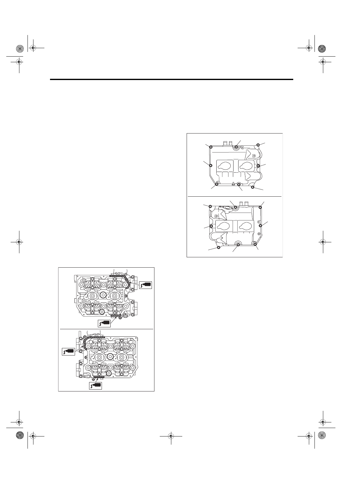
42) Install the rocker cover.
(1) Install the rocker cover gasket to the rocker
cover. (outer section and ignition coil section)
NOTE:
Use a new rocker cover gasket.
(2) Apply liquid gasket to the specified point of
the cylinder head.
NOTE:
Install within 5 min. after applying liquid gasket.
Liquid gasket:
THREE BOND 1217G (Part No. K0877Y0100)
or equivalent
(3) Install the rocker cover onto cylinder heads.
Ensure the gasket is properly positioned during
installation.
(4) Temporarily tighten the rocker cover bolts in
alphabetical order shown in the figure, and then
tighten to specified torque in alphabetical order.
Tightening torque:
6.4 N·m (0.7 kgf-m, 4.7 ft-lb)
ME-05981
ME-05982
(E)
(F)
(H)
(G)
(D),(L)
(A),(I)
(C),(K)
(B),(J)
(B),(J)
(H)
(F)
(C),(K)
(E)
(A),(I)
(D),(L)
(G)
ME(STI)-93
Cylinder Block
MECHANICAL
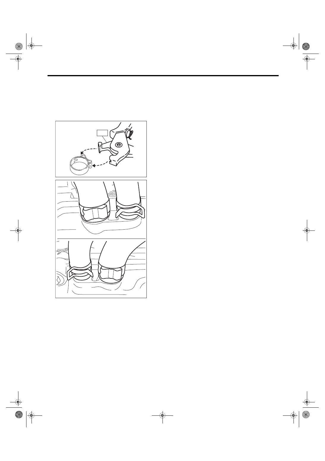
43) Connect the PCV hose (A) and vacuum hose
(B) to the rocker cover.
NOTE:
Use a new clamp for the PCV hose (A), fit the cut
out in the ST with the protrusion on the clamp as
shown in the figure, and lock the clamp.
ST 18353AA000 CLAMP PLIERS
44) Install the timing belt cover. <Ref. to ME(STI)-
49, INSTALLATION, Timing Belt Cover.>
45) Install the crank pulley. <Ref. to ME(STI)-47,
46) Install the intake manifold. <Ref. to FU(STI)-21,
INSTALLATION, Intake Manifold.>
47) Install the rear side belt. <Ref. to ME(STI)-41,
REAR SIDE BELT, INSTALLATION, V-belt.>
48) Install the engine to the vehicle. <Ref. to
ME(STI)-34, INSTALLATION, Engine Assembly.>
ME-04374
ST
ME-05768
(A)
(B)
(A)
(B)
Нет комментариевНе стесняйтесь поделиться с нами вашим ценным мнением.
Текст