Subaru Impreza 3 / Impreza WRX / Impreza WRX STI. Service manual — part 147
EC(w/o STI)-21
Leak Check Valve Assembly
EMISSION CONTROL (AUX. EMISSION CONTROL DEVICES)
D: ASSEMBLY
Assemble the parts in the reverse order of disas-
sembly while being careful of the following.
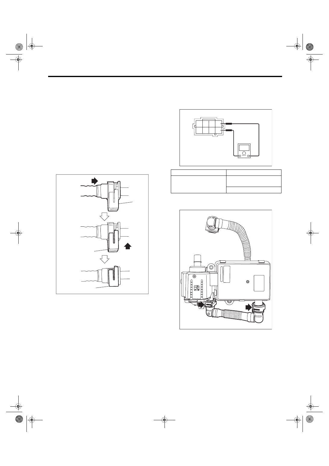
• Connect the quick connector as shown in the fig-
ure.
CAUTION:
• Check that there is no damage or dust on the
quick connector. If necessary, clean the seal
surface of the pipe.
• When connecting the quick connector, se-
curely insert the pipe all the way before locking
the retainer.
• When it is difficult to lock the retainer, make
sure that the pipe is securely inserted.
• Make sure that the quick connector is secure-
ly connected.
E: INSPECTION
1. CHECK SWITCHING VALVE
1) Check the resistance between switching valve
terminals.
2) Disconnect the drain tube from the leak check
valve assembly.
(a) Retainer
EC-02295
(a)
(a)
(a)
Terminal No.
Standard
1 and 5
27
+3
–2
Ω
(when 20°C (68°F))
31±4 Ω (when 60°C (140°F))
EC-02989
4 3
1
8 7 6 5
2
EC-02990
EC(w/o STI)-22
Leak Check Valve Assembly
EMISSION CONTROL (AUX. EMISSION CONTROL DEVICES)
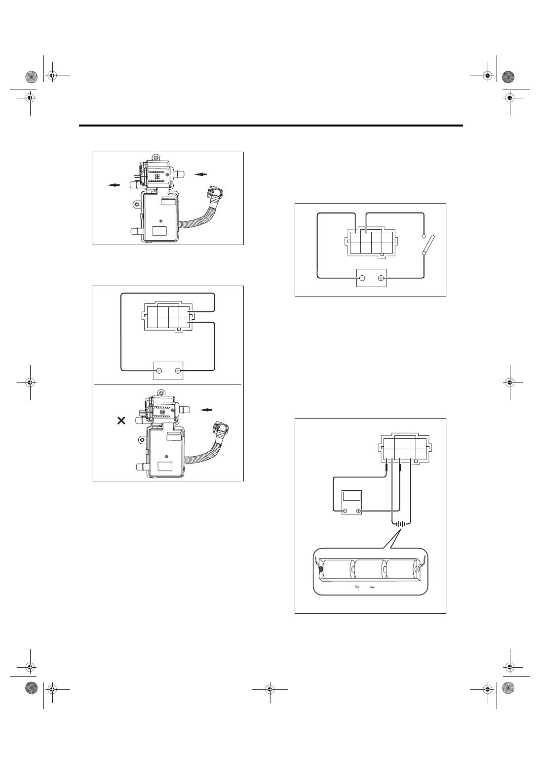
3) Check that air is discharged from (B) when air is
blown into (A).
4) Connect the battery positive terminal to the ter-
minal No. 5 and the battery negative terminal to the
terminal No. 1. Check that air does not come out
from (B) when air is blown into (A).
2. CHECK VACUUM PUMP
1) Connect the battery positive terminal to terminal
No. 3 and the battery ground terminal to terminal
No. 4, and inspect the vacuum pump operation.
CAUTION:
Do not operate the vacuum pump for 5 minutes
or more.
3. CHECK PRESSURE SENSOR
1) Connect dry-cell battery positive terminal to ter-
minal No. 6 and dry-cell battery ground terminal to
terminal No. 8, circuit tester positive terminal to ter-
minal No. 7 and the circuit tester negative terminal
to terminal No. 8.
NOTE:
• Use new dry-cell batteries.
• Using circuit tester, check the voltage of a single
dry-cell battery is 1.6 V or more. And also check the
voltage of three batteries in series is between 4.8 V
and 5.2 V.
EC-03405
(A)
(B)
EC-03406
(A)
(B)
4 3
1
8 7 6 5
2
EC-02993
4 3
1
8 7 6 5
2
EC-02994
4.8 5.2V
1.5V
1.5V
1.5V
4 3
1
8 7 6 5
2
V
EC(w/o STI)-23
Leak Check Valve Assembly
EMISSION CONTROL (AUX. EMISSION CONTROL DEVICES)
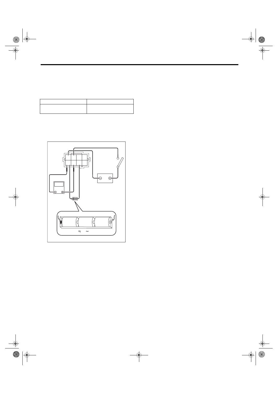
2) Check the voltage at a normal atmospheric pres-
sure.
NOTE:
The atmospheric pressure at higher altitude is low-
er than normal. Therefore, the voltage is lower than
the standard value.
3) Connect the battery positive terminal to terminal
No. 3 and the battery ground terminal to terminal
No. 4, and check that there is a voltage drop from
the voltage measured in step 2) when the vacuum
pump is operated.
4. OTHER INSPECTIONS
Check that the drain tube has no cracks, damage
or loose part.
Terminal No.
Standard
7 (+) and 8 (–)
Approx. 3.5 V
(when 25°C (77°F))
EC-02995
4.8 5.2V
1.5V
1.5V
1.5V
4 3
1
8 7 6 5
2
V
EC(w/o STI)-24
Drain Separator
EMISSION CONTROL (AUX. EMISSION CONTROL DEVICES)
12.Drain Separator
A: REMOVAL
1) Lift up the vehicle.
2) Remove the rear differential. <Ref. to DI-22, RE-
MOVAL, Rear Differential (T-type).>
3) Disconnect the drain hose from the connector.
4) Remove the drain separator from the vehicle.
B: INSTALLATION
Install in the reverse order of removal.
Tightening torque:
7.5 N·m (0.8 kgf-m, 5.5 ft-lb)
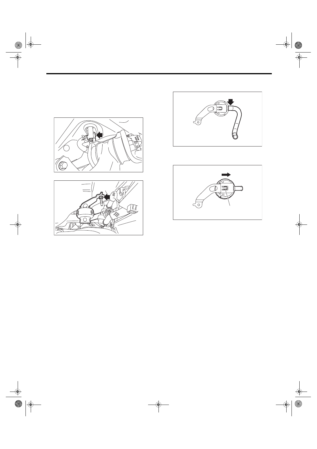
C: DISASSEMBLY
1) Remove the drain hose from the drain separator.
2) Lift up the claw (A) of the drain separator and
slide the drain separator in the direction of the ar-
row to remove the drain separator.
D: ASSEMBLY
Assemble in the reverse order of disassembly.
E: INSPECTION
1) Check that the drain separator and drain separa-
tor bracket have no deformation, crack, or other
damage.
2) Check that the drain hose has no crack, dam-
age, or looseness.
3) Check that no foreign substances are clogged in
the drain separator.
EC-02715
EC-03163
EC-03164
EC-03165
(A)
Нет комментариевНе стесняйтесь поделиться с нами вашим ценным мнением.
Текст