Subaru Impreza 3 / Impreza WRX / Impreza WRX STI. Service manual — part 146
EC(w/o STI)-17
Pressure Control Solenoid Valve Assembly
EMISSION CONTROL (AUX. EMISSION CONTROL DEVICES)
8. Pressure Control Solenoid
Valve Assembly
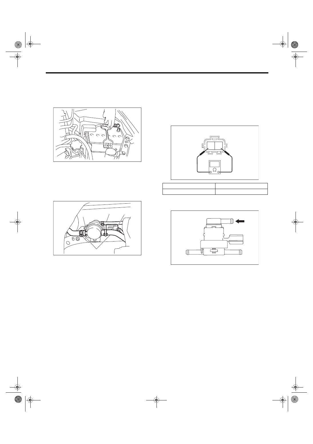
A: REMOVAL
1) Disconnect the ground cable from battery.
2) Lift up the vehicle.
3) Disconnect the connector (A) and evaporation
hose (B) from the pressure control solenoid valve
assembly.
4) Remove the nut (C) securing the bracket to the
fuel tank and remove the pressure control solenoid
valve assembly.
B: INSTALLATION
Install in the reverse order of removal.
Tightening torque:
7.35 N·m (0.7 kgf-m, 5.4 ft-lb)
C: INSPECTION
1. PRESSURE CONTROL SOLENOID
VALVE ASSEMBLY
1) Check that the pressure control solenoid valve
assembly has no deformation, cracks or other dam-
ages.
2) Check the resistance between the pressure con-
trol solenoid valve assembly terminals.
3) Connect the Mighty Vac to fuel tank side of the
pressure control solenoid valve assembly.
4) Using the Mighty Vac, generate the positive
pressure. Check that the Mighty Vac gauge needle
rises at the pressure (0.55 — 1.55 kPa (0.006 —
0.016 kgf/cm
2
, 0.08 — 0.23 psi)) then lowers.
5) Using the Mighty Vac, generate the vacuum
pressure. Check that the Mighty Vac gauge needle
does not rise.
2. OTHER INSPECTIONS
Check that the evaporation hose has no cracks,
damage or loose part.
IN-00203
EC-03067
(A)
(B)
(B)
(C)
Terminal No.
Standard
1 and 2
20 — 30 Ω
(A) Fuel tank side
(B) Canister side
(C) Atmospheric pressure
EC-02454
2 1
EC-03225
(B)
(A)
(C)
EC(w/o STI)-18
Drain Filter
EMISSION CONTROL (AUX. EMISSION CONTROL DEVICES)
9. Drain Filter
A: SPECIFICATION
The leak check valve assembly is a non-disassem-
bled part. Do not remove the drain filter from the
leak check valve assembly. Refer to “Canister” for
removal and installation procedures. <Ref. to
EC(w/o STI)-19
Shut Valve
EMISSION CONTROL (AUX. EMISSION CONTROL DEVICES)
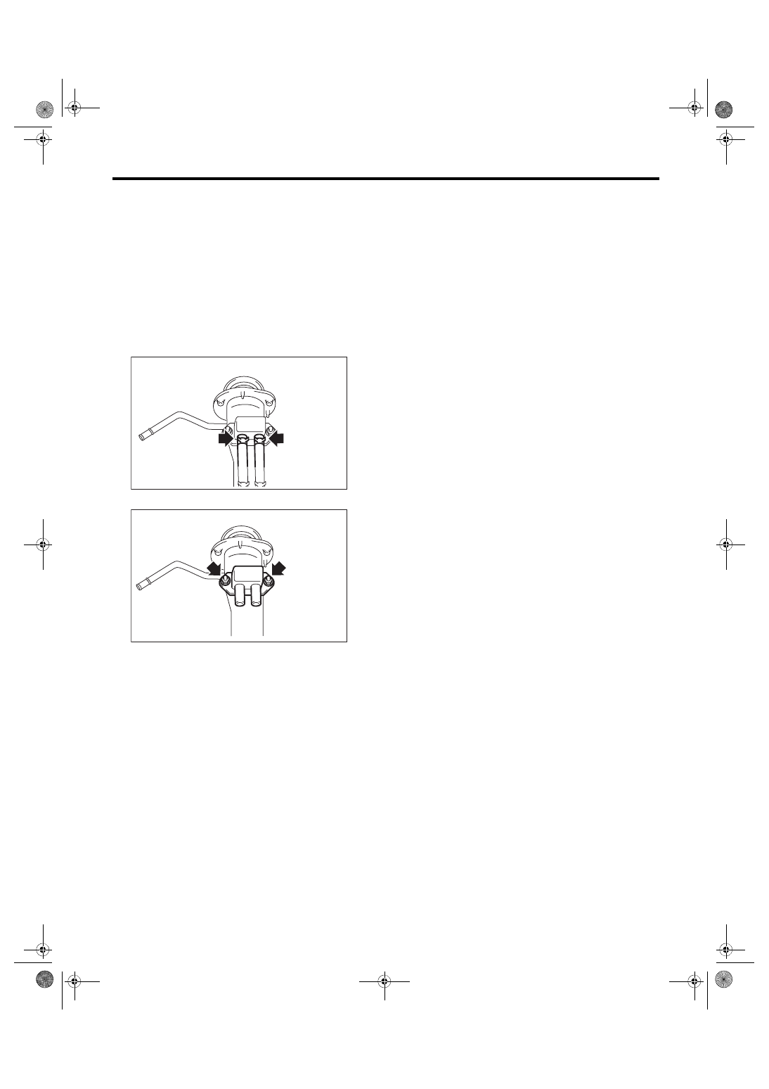
10.Shut Valve
A: REMOVAL
WARNING:
Place “NO OPEN FLAMES” signs near the
working area.
CAUTION:
Be careful not to spill fuel.
1) Remove the fuel filler pipe. <Ref. to FU(w/o STI)-
75, REMOVAL, Fuel Filler Pipe.>
2) Disconnect the evaporation hose from the shut
valve.
3) Remove the shut valve from the fuel filler pipe.
B: INSTALLATION
Install in the reverse order of removal.
Tightening torque:
4.5 N·m (0.5 kgf-m, 3.3 ft-lb)
C: INSPECTION
1) Check that the shut valve has no deformation,
cracks or other damages.
2) Check that the evaporation hose has no cracks,
damage or loose part.
EC-02753
EC-02481
EC(w/o STI)-20
Leak Check Valve Assembly
EMISSION CONTROL (AUX. EMISSION CONTROL DEVICES)
11.Leak Check Valve Assembly
A: REMOVAL
Refer to “Canister” for removal procedures. <Ref.
to EC(w/o STI)-7, REMOVAL, Canister.>
B: INSTALLATION
Refer to “Canister” for installation procedures.
<Ref. to EC(w/o STI)-9, INSTALLATION, Canis-
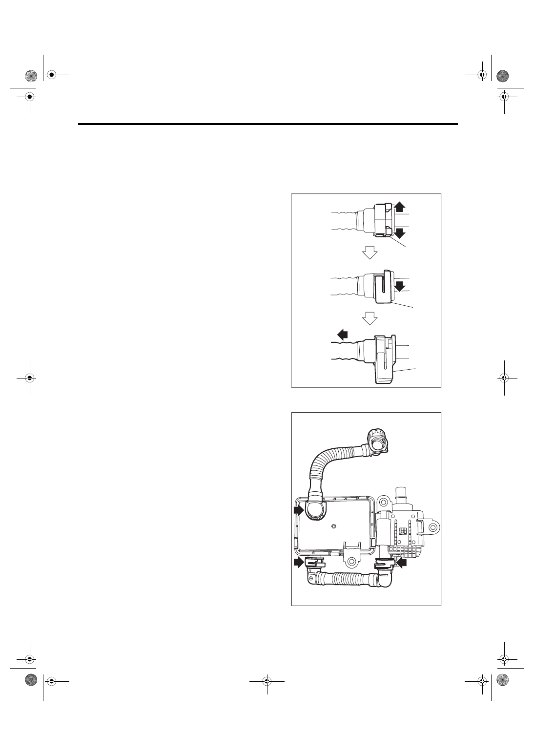
C: DISASSEMBLY
Disconnect the drain tube from the leak check
valve assembly.
NOTE:
Disconnect the quick connector as shown in the fig-
ure.
(a) Retainer
EC-02281
(a)
(a)
(a)
EC-02988
Нет комментариевНе стесняйтесь поделиться с нами вашим ценным мнением.
Текст