Subaru Impreza 3 / Impreza WRX / Impreza WRX STI. Service manual — part 148
EC(w/o STI)-25
PCV Hose Assembly
EMISSION CONTROL (AUX. EMISSION CONTROL DEVICES)
13.PCV Hose Assembly
A: REMOVAL
CAUTION:
Do not remove unless the hose and the diag-
nostics connector are broken.
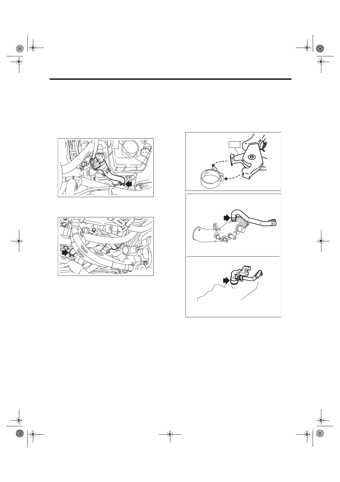
1) Disconnect the connector (A) from the PCV hose
assembly A, and remove the PCV hose assembly
A from the rocker cover RH.
2) Disconnect the connector (A) from the PCV hose
assembly B, and remove the PCV hose assembly
B from the rocker cover LH.
3) Remove the intake manifold. <Ref. to FU(w/o
STI)-18, REMOVAL, Intake Manifold.>
4) Remove the turbocharger. <Ref. to IN(w/o STI)-
5) Remove the intake duct. <Ref. to IN(w/o STI)-
6) Remove the PCV hose assembly C from the in-
take duct and the cylinder block RH.
NOTE:
Pinch the clamp of the PCV hose assembly C by fit-
ting the cut out in the ST with the protrusion on the
clamp as shown in the figure, and unlock the
clamp.
ST 18353AA000 CLAMP PLIERS
EC-02996
(A)
EC-02997
(A)
ME-04374
ST
EC-02735
EC(w/o STI)-26
PCV Hose Assembly
EMISSION CONTROL (AUX. EMISSION CONTROL DEVICES)
B: INSTALLATION
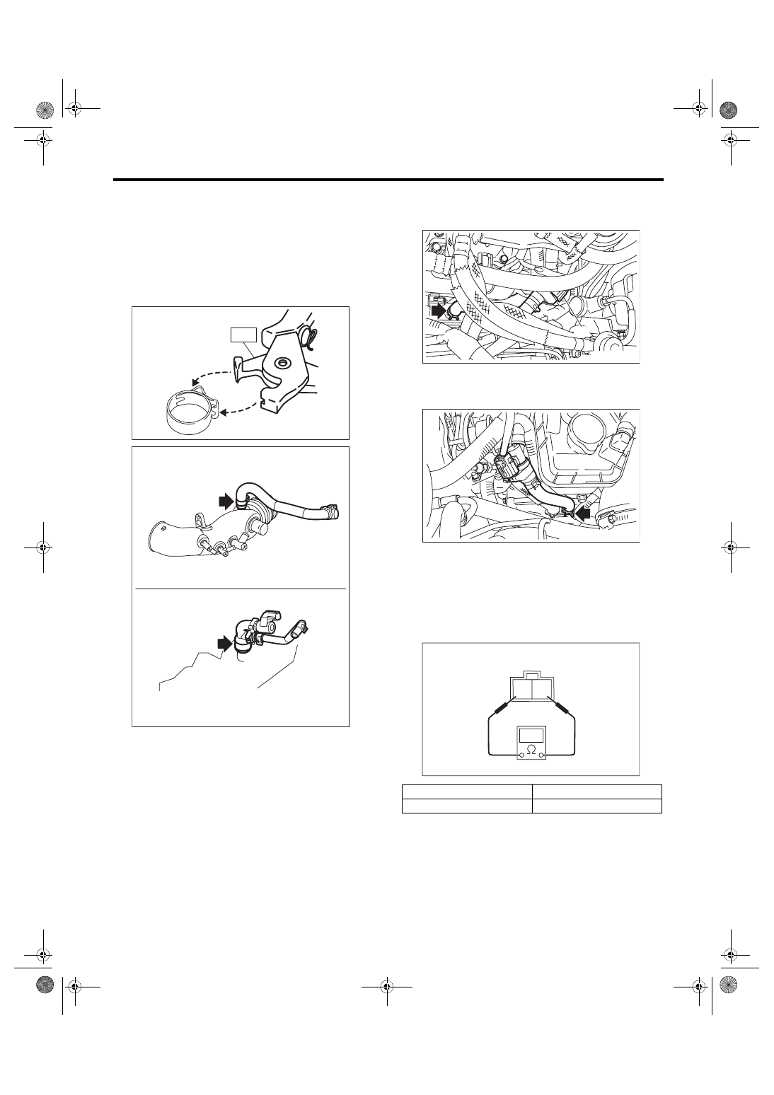
1) Install the PCV hose assembly C to the intake
duct and the cylinder block RH.
NOTE:
Use a new clamp for the PCV hose assembly C, fit
the cut out in the ST with the protrusion on the
clamp as shown in the figure, and lock the clamp.
ST 18353AA000 CLAMP PLIERS
2) Install the intake duct. <Ref. to IN(w/o STI)-11,
3) Install the turbocharger. <Ref. to IN(w/o STI)-15,
4) Install the intake manifold. <Ref. to FU(w/o STI)-
22, INSTALLATION, Intake Manifold.>
5) Install the PCV hose assembly B to the rocker
cover LH, and connect the connector (A) to the
PCV hose assembly B.
6) Install the PCV hose assembly A to the rocker
cover RH, and connect the connector (A) to the
PCV hose assembly A.
C: INSPECTION
1. DIAGNOSIS CONNECTOR
1) Check that the diagnosis connector has no de-
formation, cracks and any other damage.
2) Check the resistance between the diagnosis
connector terminals.
2. OTHER INSPECTIONS
1) Check that the PCV connector has no deforma-
tion, cracks or other damages.
2) Check that the hose has no cracks, damage or
loose part.
ME-04374
ST
EC-02735
Terminal No.
Standard
1 and 2
Less than 1 Ω
EC-02997
(A)
EC-02996
(A)
2 1
EC-02428
EC(w/o STI)-27
PCV Valve
EMISSION CONTROL (AUX. EMISSION CONTROL DEVICES)
14.PCV Valve
A: REMOVAL
CAUTION:
Do not remove unless the PCV valve is broken.
1) Remove the intake manifold. <Ref. to FU(w/o
STI)-18, REMOVAL, Intake Manifold.>
2) Remove the secondary air combination valve
RH. <Ref. to EC(w/o STI)-30, REMOVAL, Second-
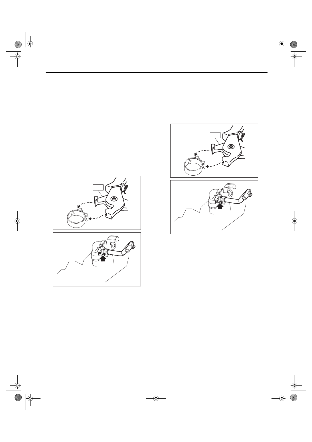
3) Disconnect the vacuum hose (A) from the PCV
valve and remove the PCV valve from the PCV
connector.
NOTE:
Pinch the clamp of the PCV connector by fitting the
cut out in the ST with the protrusion on the clamp as
shown in the figure, and unlock the clamp.
ST 18353AA000 CLAMP PLIERS
B: INSTALLATION
1) Install the PCV valve to the PCV connector and
connect the vacuum hose (A) to the PCV valve.
NOTE:
Use a new clamp for the PCV connector clamp, fit
the cut out in the ST with the protrusion on the
clamp as shown in the figure, and lock the clamp.
ST 18353AA000 CLAMP PLIERS
2) Install the secondary air combination valve RH.
<Ref. to EC(w/o STI)-31, INSTALLATION, Second-
3) Install the intake manifold. <Ref. to FU(w/o STI)-
22, INSTALLATION, Intake Manifold.>
4) Install the collector cover.
ME-04374
ST
EC-02736
(A)
ME-04374
ST
EC-02736
(A)
EC(w/o STI)-28
PCV Valve
EMISSION CONTROL (AUX. EMISSION CONTROL DEVICES)
C: INSPECTION
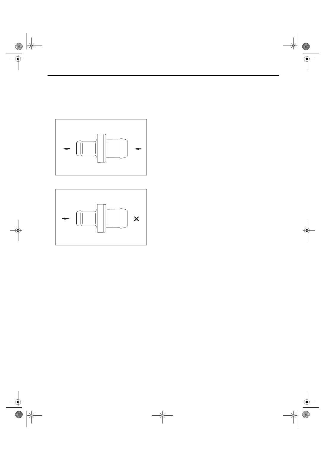
1. PCV VALVE
1) Check that the PCV valve has no deformation,
cracks or other damages.
2) Check that air is discharged from (B) when air is
blown into (A).
3) Check that air does not come out from (B) when
air is blown into (A).
2. OTHER INSPECTIONS
Check the vacuum hose for cracks, damage or
looseness.
EC-02507
(B)
(A)
EC-02508
(A)
(B)
Нет комментариевНе стесняйтесь поделиться с нами вашим ценным мнением.
Текст