Subaru Impreza 3 / Impreza WRX / Impreza WRX STI. Service manual — part 779
LAN(diag)-25
Subaru Select Monitor
LAN SYSTEM (DIAGNOSTICS)
B: INSPECTION
1. COMMUNICATION FOR INITIALIZING IMPOSSIBLE
DETECTING CONDITION:
Defective harness connector
TROUBLE SYMPTOM:
Not communicable with Subaru Select Monitor.
WIRING DIAGRAM:
• SECURITY SYSTEM <Ref. to WI-154, WIRING DIAGRAM, Security System.>
• CAN communication system <Ref. to WI-171, WIRING DIAGRAM, CAN Communication System.>
Step
Check
Yes
No
1
CHECK IGNITION SWITCH.
Is the ignition switch ON?
Turn the ignition
switch to ON, and
select Integ. unit
mode using Sub-
aru Select Monitor.
2 3 4 5
1
6 7 8
i97
*
1
i97
*
1
*
1
B225
13
14
15 16
17
27
24
25
26
20
21
22
23
29
30
31
28
32 35
33
34
37
38
39
36
40
8
9
10
11 12
1
2
5
3
4
7
6
19
18
3
4
10A
B225
i84
A:
B20
B6
A: i84
1 2
3 4
5 6
7 8
9 10 11 12
14 15 16 17 18 19 20 21 22 23
24 25
26 27 28 29
30 31 32 33
34 35
13
A2
8
C2
B280
B:
6
4 5
3
1 2
9
7 8
17
6
1
5
1
4
1
3
1
2
1
1
1
0
1
20
9
1
8
1
24
3
2
2
2
1
2
26
5
2
4
5
7
8
6
1
B40
D27
B17
C20
B40
1 2 3 4 5 6 7 8
9 0
1
1
1
2
1
3
1
4
1
5
1
6
1
5
7
6
4
8
2
1
9
3
0
1
3
2
2
2
1
1
2
1
3
1
4
1
5
1
7
2
6
2
5
2
4
2
6
1
7
1
8
1
9
2
8
2
9
1
0
2
21
30
B279
D:
7
5 6
8
2
1
9
4
3
0
1
4
2
5
2
3
2
2
2
1
1
2
1
3
1
4
1
5
1
8
2
7
2
6
2
6
1
7
1
8
1
9
1
1
2
0
2
B281
C:
D: B279
B: B280 C: B281
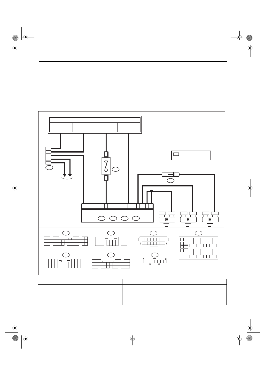
LAN00603
MB-27
M/B FUSE NO. 13
(B)
FB-32
F/B FUSE NO. 4
(IG)
MB-29
M/B FUSE NO. 8
(B)
TO POWER SUPPLY CIRCUIT
BODY INTEGRATED UNIT
DATA LINK
CONNECTOR
REF. TO ENGINE
ELECTRICAL
SYSTEM
FB-18
F/B FUSE NO. 7
(B)
FUSE (RELA
Y BLOCK)
RELAY BLOCK
JOINT GROUND
CONNECTOR
: TERMINAL No. OPTIONAL
ARRANGEMENT
LAN(diag)-26
Subaru Select Monitor
LAN SYSTEM (DIAGNOSTICS)
2
CHECK BATTERY.
1) Turn the ignition switch to OFF.
2) Measure the battery voltage.
Is the voltage 11 V or more?
Charge or replace
the battery.
3
CHECK BATTERY TERMINAL.
Is there poor contact at battery
terminal?
Repair or tighten
the battery termi-
nal.
4
CHECK COMMUNICATION OF SUBARU SE-
LECT MONITOR.
1) Turn the ignition switch to ON.
2) Using the Subaru Select Monitor, check
whether communication to other systems can
be executed normally.
Is the system name displayed? Go to step
5
CHECK COMMUNICATION OF SUBARU SE-
LECT MONITOR.
1) Turn the ignition switch to OFF.
2) Disconnect the body integrated unit connec-
tor.
3) Turn the ignition switch to ON.
4) Check whether communication to other sys-
tems can be executed normally.
Is the system name displayed? Go to step
6
CHECK HARNESS CONNECTOR BETWEEN
EACH CONTROL MODULE AND SUBARU
SELECT MONITOR.
1) Turn the ignition switch to OFF.
2) Measure the resistance between data link
connector and chassis ground.
Connector & terminal
(B40) No. 7 — Chassis ground:
Is the resistance 1 MΩ or
more?
Repair the harness
and connector
between each con-
trol module and
Subaru Select
Monitor.
7
CHECK OUTPUT SIGNAL TO BODY INTE-
GRATED UNIT.
1) Turn the ignition switch to ON.
2) Measure the voltage between data link con-
nector and chassis ground.
Connector & terminal
(B40) No. 7 (+) — Chassis ground (–):
Is the voltage less than 1 V?
Repair the harness
and connector
between each con-
trol module and
Subaru Select
Monitor.
8
CHECK HARNESS CONNECTOR BETWEEN
BODY INTEGRATED UNIT AND DATA LINK
CONNECTOR.
1) Turn the ignition switch to OFF.
2) Measure the resistance between body inte-
grated unit and data link connector.
Connector & terminal
(B40) No. 7 — (B280) No. 20:
Is the resistance less than 1 Ω? Go to step
Repair the harness
and connector
between body inte-
grated unit and
Subaru Select
Monitor.
9
CHECK BACK-UP FUSE.
Check that back-up fuse is not blown out, or
check that it is inserted.
Is back-up fuse OK?
Replace the back-
up fuse, or insert it
into the fuse
holder.
10
CHECK POWER SUPPLY CIRCUIT.
1) Connect the body integrated unit.
2) Measure the voltage between body inte-
grated unit connector and chassis ground.
Connector & terminal
(B280) No. 6 (+) — Chassis ground (–):
(B281) No. 2 (+) — Chassis ground (–):
Is the voltage 10 V or more?
Repair the open
circuit of harness
between body inte-
grated unit and
battery.
Step
Check
Yes
No
LAN(diag)-27
Subaru Select Monitor
LAN SYSTEM (DIAGNOSTICS)
CAUTION:
For model with immobilizer, immobilizer registration work is necessary when the body integrated
unit replaced. For operation procedures, refer to “REGISTRATION MANUAL FOR IMMOBILIZER”.
11
CHECK HARNESS CONNECTOR BETWEEN
BODY INTEGRATED UNIT AND CHASSIS
GROUND.
1) Turn the ignition switch to OFF.
2) Disconnect the connector from body inte-
grated unit.
3) Measure the resistance of harness between
the body integrated unit and chassis ground.
Connector & terminal
(i84) No. 28 — Chassis ground:
(B279) No. 27 — Chassis ground:
(B280) No. 17 — Chassis ground:
(B281) No. 20 — Chassis ground:
Is the resistance 1 MΩ or
more?
Repair the poor
contact of harness
between body inte-
grated unit and
ground.
12
CHECK POOR CONTACT OF CONNECTOR. Is there poor contact of the con-
trol unit ground and the Subaru
Select Monitor?
Repair the poor
contact of connec-
tor.
Replace the body
integrated unit.
<Ref. to SL-48,
REMOVAL, Body
Integrated Unit.>
Step
Check
Yes
No
LAN(diag)-28
Read Diagnostic Trouble Code (DTC)
LAN SYSTEM (DIAGNOSTICS)
7. Read Diagnostic Trouble
Code (DTC)
A: OPERATION
For details concerning DTC reading procedure, re-
fer to “Subaru Select Monitor”. <Ref. to LAN(diag)-
Нет комментариевНе стесняйтесь поделиться с нами вашим ценным мнением.
Текст