Subaru Impreza 3 / Impreza WRX / Impreza WRX STI. Service manual — part 389
CS-7
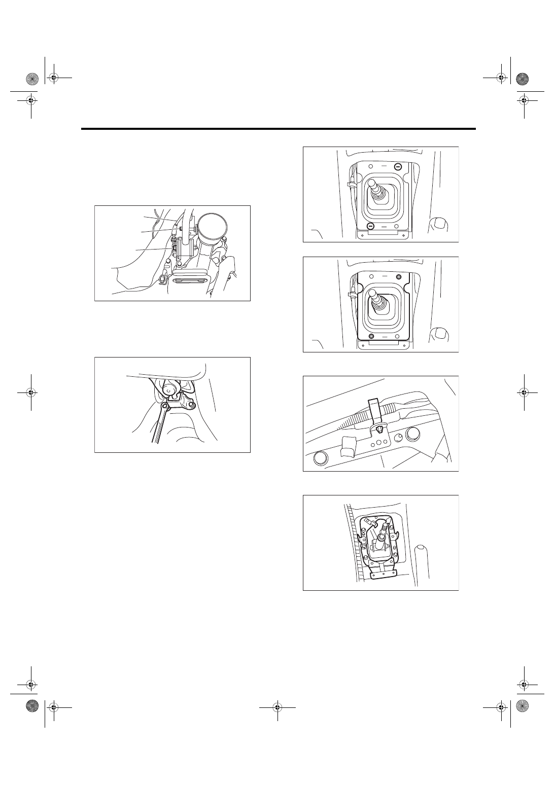
MT Gear Shift Lever
CONTROL SYSTEMS
15) Move the transmission to the right side, and re-
move the joint COMPL, stay bolts and reverse
check cable.
NOTE:
If the transmission is not moved aside, the joint
COMPL and stay bolts may contact the body and
cause damage.
16) Remove the cushion rubber from the body.
17) Lower the vehicle.
18) Remove the gear shift lever.
2. EXCEPT FOR STI MODEL
1) Disconnect the ground cable from battery.
2) Remove the gear shift knob.
3) Remove the console box. <Ref. to EI-51, RE-
4) Remove the console side cover and console
front panel. <Ref. to EI-52, CONSOLE FRONT
PANEL, REMOVAL, Center Console.>
5) Remove the clamp.
6) Remove the boot and insulator assembly.
7) Remove the harness clamp from the plate COM-
PL.
8) Remove the plate COMPL from the vehicle
body.
9) Lift up the vehicle.
10) Remove the center exhaust pipe (rear). <Ref.
to EX(w/o STI)-2, General Description.>
(A) Joint COMPL bolt
(B) Stay bolt
(C) Reverse check cable
CS-00221
(C)
(A)
(B)
CS-00222
CS-00731
CS-00732
CS-00313
CS-00869
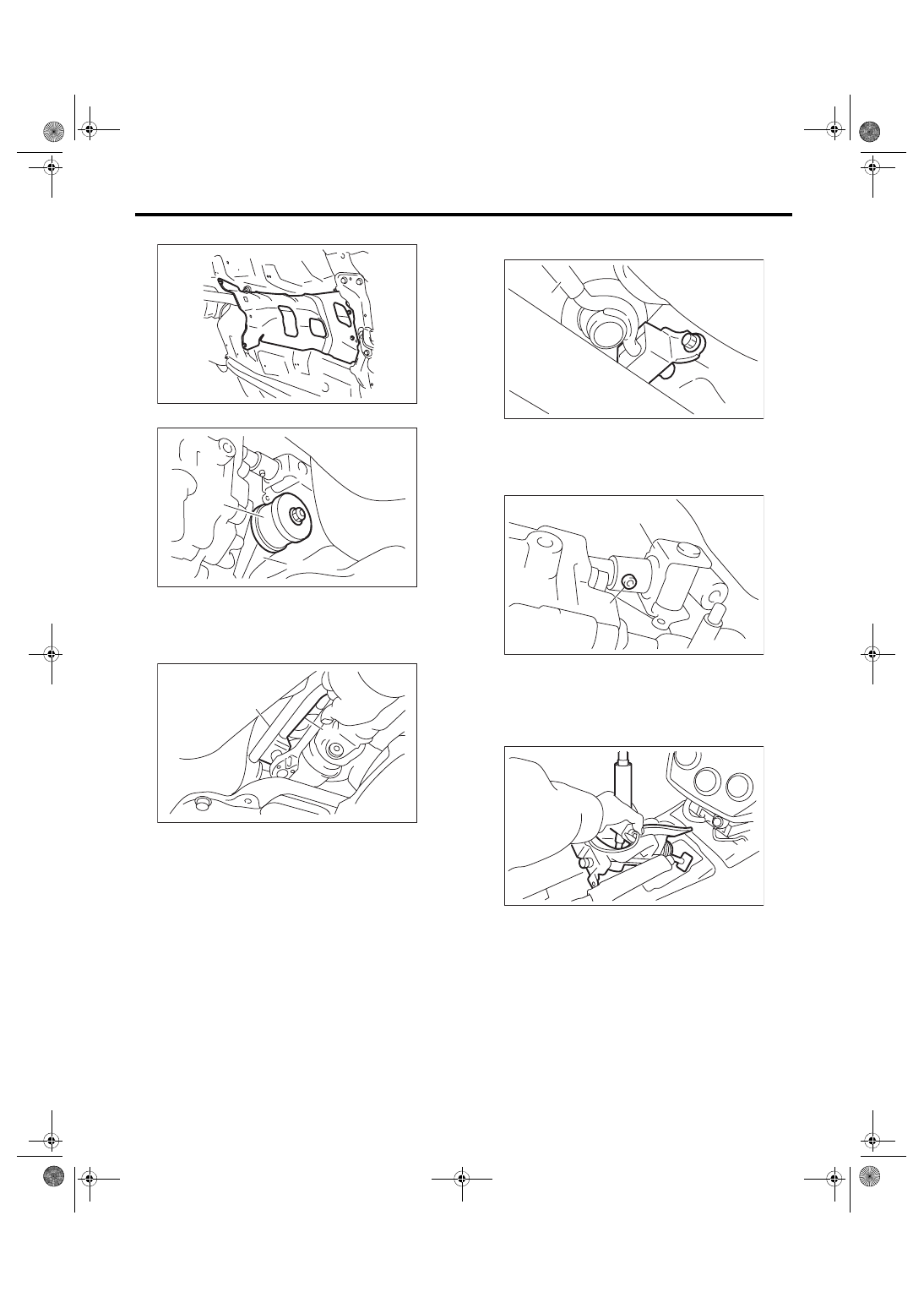
CS-8
MT Gear Shift Lever
CONTROL SYSTEMS
11) Remove the heat shield cover.
12) Remove the stay from transmission bracket.
13) Remove the rod from joint.
14) Remove the cushion rubber from the vehicle
body.
15) Extract the spring pin and remove the joint.
16) Lower the vehicle.
17) Remove the gear shift lever.
(A) Stay
(B) Transmission bracket
(A) Stay
(B) Rod
MT-01660
MT-02037
(A)
(B)
CS-00051
(A)
(B)
(A) Stay
(B) Cushion rubber
(A) Joint
(B) Spring pin
CS-00052
(A)
(B)
CS-00053
(A)
(B)
CS-00870
CS-9
MT Gear Shift Lever
CONTROL SYSTEMS
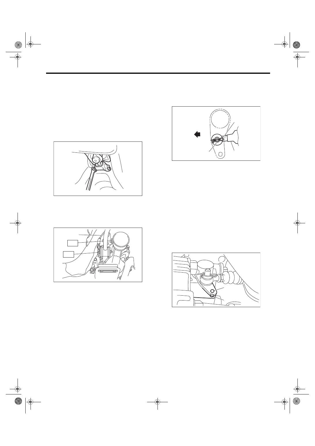
B: INSTALLATION
1. STI MODEL
1) Insert the gear shift lever from the room side.
NOTE:
After inserting the rod and stay, temporarily put
them onto transmission mount.
2) Lift up the vehicle.
3) Mount the cushion rubber on the body.
Tightening torque:
18 N·m (1.8 kgf-m, 13.3 ft-lb)
4) Move the transmission to the right side of the ve-
hicle, and install the joint COMPL and stay.
Tightening torque:
T1: 12 N·m (1.2 kgf-m, 8.9 ft-lb)
T2: 32 N·m (3.3 kgf-m, 23.6 ft-lb)
5) Install the reverse check cable, washer and snap
pin to the reverse check lever.
NOTE:
Pay attention to the installing direction of the snap
ring.
6) Make sure the hole of extension case is aligned
with that of reverse check lever. If the hole posi-
tions are not aligned, adjust the reverse check ca-
ble. <Ref. to CS-27, ADJUSTMENT, Reverse
Check Cable.>
NOTE:
• Check that the M3 bolt goes through the hole of
reverse check lever and can be inserted into the
hole of extension case.
• When checking visually, confirm that the gap of
hole positions is 0.5 mm (0.02 in) or less.
7) Install the crossmember. <Ref. to 6MT-29, IN-
STALLATION, Transmission Mounting System.>
(A) Reverse check cable
CS-00222
CS-00223
(A)
T1
T2
(A) Reverse check cable
(B) Washer
(C) Snap pin
(D) Front side
(A) Hole of reverse check lever
(B) Hole of extension case
CS-00224
(B)
(D)
(C)
(A)
(A)
(B)
CS-01751
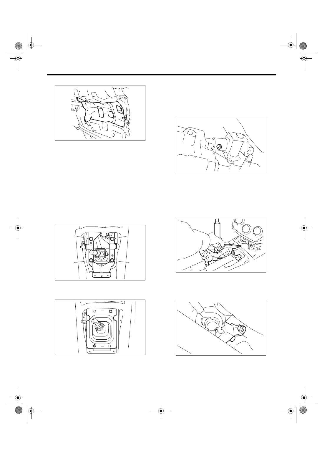
CS-10
MT Gear Shift Lever
CONTROL SYSTEMS
8) Install the heat shield cover.
9) Install the center exhaust pipe. <Ref. to EX(w/o
10) Install the under cover.
11) Install the plate COMPL.
NOTE:
Be careful not to twist the inner boot when install-
ing.
Tightening torque:
18 N·m (1.8 kgf-m, 13.3 ft-lb)
(1) Set the plate COMPL to the vehicle.
(2) Temporarily tighten the bolt (A).
(3) Tighten the bolt (B).
(4) Tighten the bolt (A).
(5) Tighten the bolts (C) and (D).
12) Install the harness clamp to the plate COMPL.
13) Install the boot and insulator assembly, and se-
cure with a clamp.
14) Install the console side cover and console front
panel. <Ref. to EI-54, INSTALLATION, Center
15) Install the console box. <Ref. to EI-51, INSTAL-
16) Install the gear shift knob.
17) Make sure the gears can be shifted accurately
into each gear.
2. EXCEPT FOR STI MODEL
1) Install the joint to the transmission and secure
with a spring pin.
2) Insert the gear shift lever from the room side.
NOTE:
Insert the rod and the stay, and then temporarily set
them onto the transmission mount.
3) Lift up the vehicle.
4) Mount the cushion rubber on the vehicle body.
Tightening torque:
18 N·m (1.8 kgf-m, 13.3 ft-lb)
MT-01660
CS-00737
(B)
(A)
(C)
(D)
CS-00927
(A) Joint
(B) Spring pin
(A) Stay
(B) Cushion rubber
CS-00053
(A)
(B)
CS-00870
CS-00052
(A)
(B)
Нет комментариевНе стесняйтесь поделиться с нами вашим ценным мнением.
Текст