Subaru Impreza 3 / Impreza WRX / Impreza WRX STI. Service manual — part 144
EC(w/o STI)-9
Canister
EMISSION CONTROL (AUX. EMISSION CONTROL DEVICES)
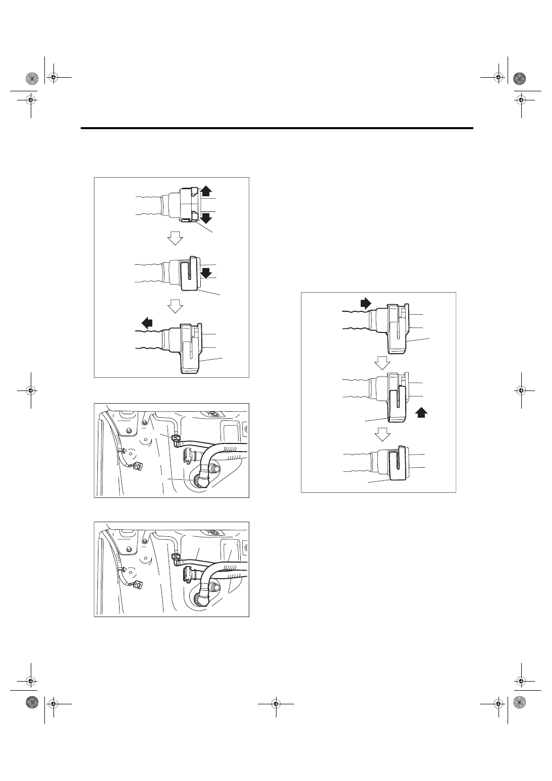
15) Disconnect purge tube (A) and vent tube (B).
NOTE:
Disconnect the quick connector as shown in the fig-
ure.
16) Remove purge tube (A), vent tube (B), and
drain tube A (C).
B: INSTALLATION
Install in the reverse order of removal while being
careful of the following.
• Connect the quick connector as shown in the fig-
ure.
CAUTION:
• Check that there is no damage or dust on the
quick connector. If necessary, clean the seal
surface of the pipe.
• When connecting the quick connector, se-
curely insert the pipe all the way before locking
the retainer.
• When it is difficult to lock the retainer, make
sure that the pipe is securely inserted.
• Make sure that the quick connector is secure-
ly connected.
(a) Retainer
EC-02281
(a)
(a)
(a)
EC-02980
(B)
(A)
EC-02981
(C)
(A)
(B)
(a) Retainer
EC-02295
(a)
(a)
(a)
EC(w/o STI)-10
Canister
EMISSION CONTROL (AUX. EMISSION CONTROL DEVICES)
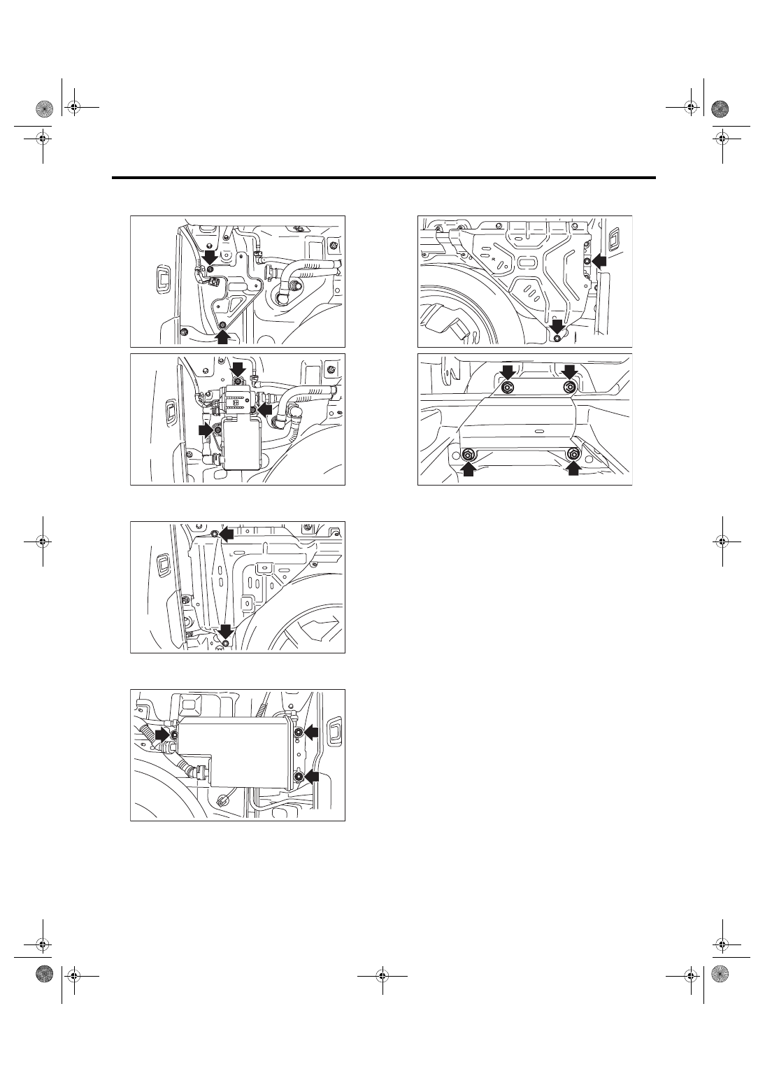
Tightening torque:
7.5 N·m (0.8 kgf-m, 5.5 ft-lb)
Tightening torque:
18 N·m (1.8 kgf-m, 13.3 ft-lb)
Tightening torque:
8 N·m (0.8 kgf-m, 5.9 ft-lb)
Tightening torque:
18 N·m (1.8 kgf-m, 13.3 ft-lb)
C: INSPECTION
1) Check that the canister and leak check valve as-
sembly have no deformation, cracks or other dam-
ages.
2) Check that the tube has no cracks, damage or
loose part.
EC-02982
EC-02983
EC-02984
EC-02985
EC-02986
EC-02987
EC(w/o STI)-11
Purge Control Solenoid Valve
EMISSION CONTROL (AUX. EMISSION CONTROL DEVICES)
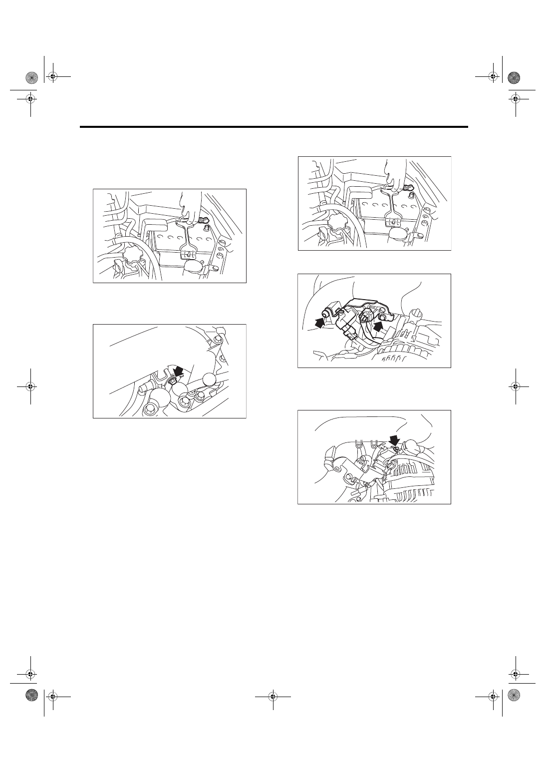
5. Purge Control Solenoid Valve
A: REMOVAL
1. PURGE CONTROL SOLENOID VALVE 1
1) Disconnect the ground cable from battery.
2) Remove the bolts which secure purge control
solenoid valve 1 to the intake manifold, and discon-
nect the connector from the purge control solenoid
valve 1.
3) Disconnect the vacuum hose from purge control
solenoid valve 1.
2. PURGE CONTROL SOLENOID VALVE 2
1) Disconnect the ground cable from battery.
2) Remove the solenoid valve bracket assembly
from the intake manifold.
3) Disconnect the connector and the vacuum hose
from purge control solenoid valve 2.
4) Remove the purge control solenoid valve 2 from
the solenoid valve bracket assembly.
IN-00203
EC-02265
IN-00203
EC-00219
EC-02266
EC(w/o STI)-12
Purge Control Solenoid Valve
EMISSION CONTROL (AUX. EMISSION CONTROL DEVICES)
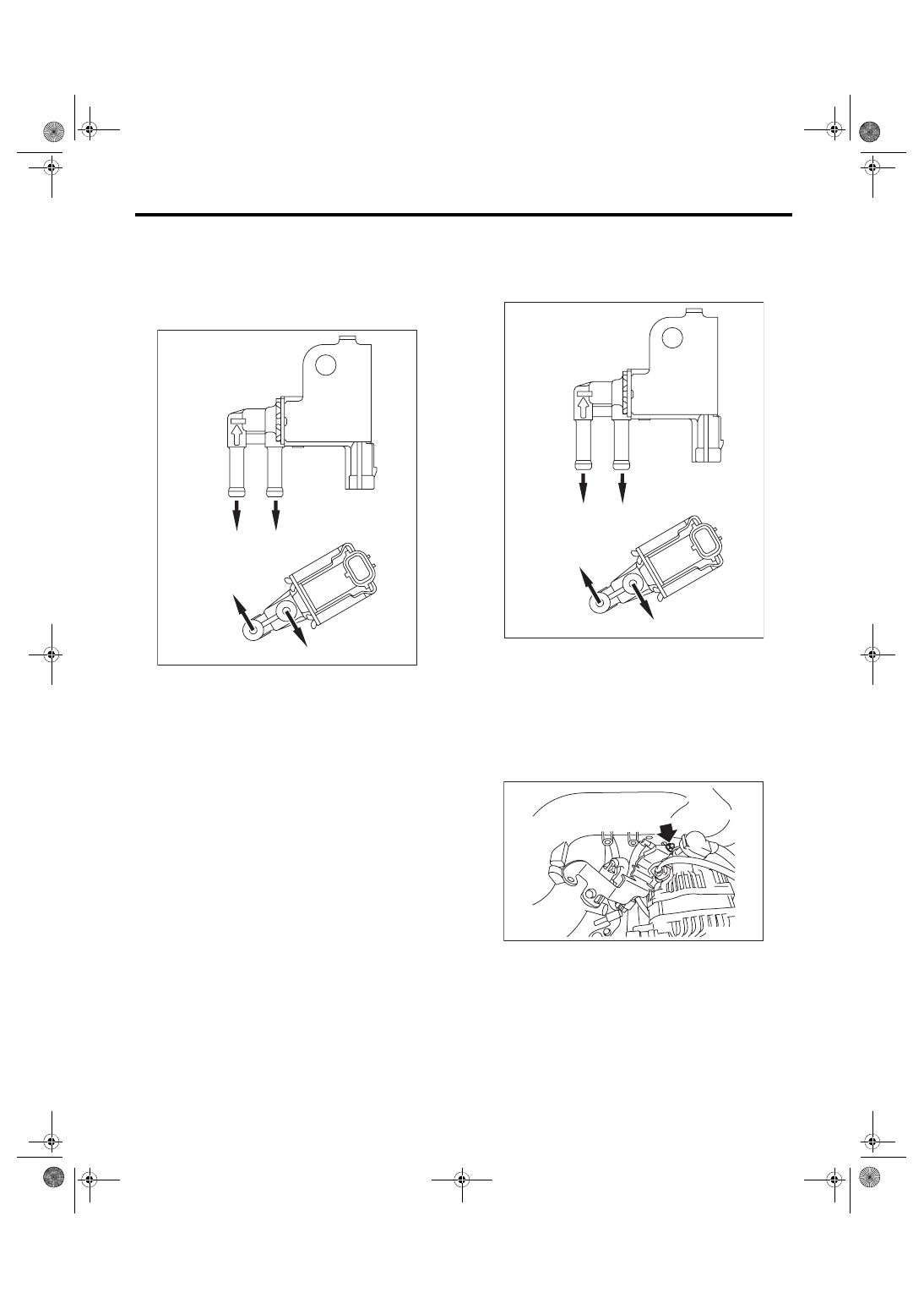
B: INSTALLATION
1. PURGE CONTROL SOLENOID VALVE 1
Install in the reverse order of removal.
NOTE:
Connect the vacuum hose as shown in the figure.
Tightening torque:
6.4 N·m (0.7 kgf-m, 4.7 ft-lb)
2. PURGE CONTROL SOLENOID VALVE 2
Install in the reverse order of removal.
NOTE:
Connect the vacuum hose as shown in the figure.
Tightening torque:
6.4 N·m (0.7 kgf-m, 4.7 ft-lb)
(A) Purge control solenoid valve 1
(B) Purge control solenoid valve 2
(a) To intake manifold
(b) To intake duct
(c) To fuel pipe
(A)
(B)
(b)
(c)
(c)
(a)
EC-02517
(A) Purge control solenoid valve 1
(B) Purge control solenoid valve 2
(a) To intake manifold
(b) To intake duct
(c) To fuel pipe
(A)
(B)
(b)
(c)
(c)
(a)
EC-02517
EC-02266
Нет комментариевНе стесняйтесь поделиться с нами вашим ценным мнением.
Текст