Subaru Impreza 3 / Impreza WRX / Impreza WRX STI. Service manual — part 289

EN(H4DOTC)(diag)-380
Diagnostic Procedure with Diagnostic Trouble Code (DTC)
ENGINE (DIAGNOSTICS)
EP:DTC P2109 THROTTLE/PEDAL POSITION SENSOR “A” MINIMUM STOP
PERFORMANCE
NOTE:
For the diagnostic procedure, refer to DTC P2101. <Ref. to EN(H4DOTC)(diag)-371, DTC P2101 THROT-
TLE ACTUATOR CONTROL MOTOR CIRCUIT RANGE/PERFORMANCE, Diagnostic Procedure with Di-
EQ:DTC P2119 THROTTLE ACTUATOR CONTROL THROTTLE BODY RANGE/
PERFORMANCE
NOTE:
For the diagnostic procedure, refer to DTC P2101. <Ref. to EN(H4DOTC)(diag)-371, DTC P2101 THROT-
TLE ACTUATOR CONTROL MOTOR CIRCUIT RANGE/PERFORMANCE, Diagnostic Procedure with Di-
Step
Check
Yes
No
1
CHECK ELECTRONIC THROTTLE CON-
TROL RELAY.
1) Turn the ignition switch to OFF.
2) Remove the electronic throttle control relay.
3) Measure the resistance between electronic
throttle control relay terminals.
Terminals
No. 29 — No. 30:
Is the resistance 1 MΩ or
more?
2
CHECK SHORT CIRCUIT OF ELECTRONIC
THROTTLE CONTROL RELAY POWER SUP-
PLY.
1) Turn the ignition switch to ON.
2) Measure the voltage between electronic
throttle control relay connector and chassis
ground.
Connector & terminal
(B220) No. 30 (+) — Chassis ground (–):
Is the voltage 10 V or more?
Repair the short
circuit to power in
the harness
between ECM con-
nector and elec-
tronic throttle
control relay con-
nector.
3
CHECK HARNESS BETWEEN ECM AND
ELECTRONIC THROTTLE CONTROL RE-
LAY CONNECTOR.
1) Turn the ignition switch to OFF.
2) Disconnect the connector from ECM.
3) Measure the resistance between ECM con-
nector and chassis ground.
Connector & terminal
(B135) No. 17 — Chassis ground:
Is the resistance 1 MΩ or
more?
Repair the poor
contact of ECM
connector.
Repair the short
circuit to ground in
harness between
ECM connector
and electronic
throttle control
relay connector.

EN(H4DOTC)(diag)-381
Diagnostic Procedure with Diagnostic Trouble Code (DTC)
ENGINE (DIAGNOSTICS)
ER:DTC P2122 THROTTLE/PEDAL POSITION SENSOR/SWITCH “D” CIRCUIT
LOW INPUT
DTC DETECTING CONDITION:
• Immediately at fault recognition
• GENERAL DESCRIPTION <Ref. to GD(H4DOTC)-255, DTC P2122 THROTTLE/PEDAL POSITION
SENSOR/SWITCH “D” CIRCUIT LOW INPUT, Diagnostic Trouble Code (DTC) Detecting Criteria.>
TROUBLE SYMPTOM:
• Improper idling
• Poor driving performance
CAUTION:
After servicing or replacing faulty parts, perform Clear Memory Mode <Ref. to EN(H4DOTC)(diag)-63,
OPERATION, Clear Memory Mode.>, and Inspection Mode <Ref. to EN(H4DOTC)(diag)-49, PROCE-
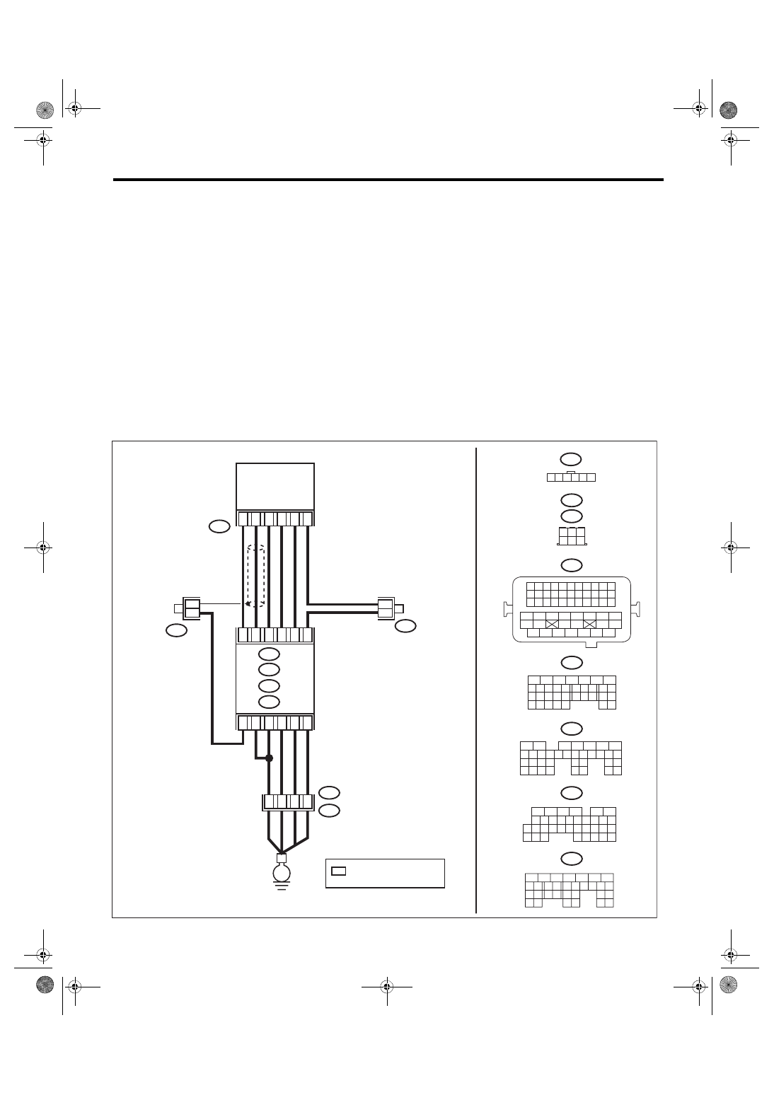
WIRING DIAGRAM:
• Engine electrical system, without SI-DRIVE <Ref. to WI-32, WITHOUT SI-DRIVE, WIRING DIAGRAM,
• Engine electrical system, with SI-DRIVE <Ref. to WI-48, WITH SI-DRIVE, WIRING DIAGRAM, Engine
EN-08749
B315
C: B136
B137
D:
B83
B315
*
*
4
6
5
1
3
2
B21
B23
B29
B22
B31
B30
A4
B21
E2
D1
B21
1 2 3 4
12 13 14 15
5 6 7 8
16 17 18 19
9 10 11
20 21 22
23 24 25 26 27 28 29 30 31 32 33
35
34
37
36
39
38
41
40
43
42
44 45
47
46
49
48
51
50
53
52
54
B137
5
6
7
8
2
1
9
4
3
10
22 23
11 12 13 14 15
24 25
26
16 17
18 19 20 21
27
28 29
30 31
B136
5
6
7 8
2
1
9
4
3
10
24
22 23
25
11 12 13 14 15
26 27
28
16
17 18 19 20 21
33 34
29
32
30
31
35
B135
5
6
7
8
2
1
9
4
3
10
24
22 23
25
11 12 13 14 15
26 27
28
16 17 18 19
20 21
29 30 31
32 33
34 35
B:
C:
D:
B122
B83
A6
C4
D3
B: B135
A: B134
A3
40
34
35
36
B122
1 2 3 4 5 6
*
*
B134
5
6
7
8
2
1
9
4
3
10
24
22 23
25
11 12 13 14 15
26 27
28
16 17
18 19 20 21
33 34
29
32
30 31
A:
*
6
4 5
3
2
1
E
ECM
: TERMINAL No.
OPTIONAL ARRANGEMENT
ACCELERATOR
PEDAL POSITION
SENSOR

EN(H4DOTC)(diag)-382
Diagnostic Procedure with Diagnostic Trouble Code (DTC)
ENGINE (DIAGNOSTICS)
Step
Check
Yes
No
1
CHECK HARNESS BETWEEN ECM AND AC-
CELERATOR PEDAL POSITION SENSOR
CONNECTOR.
1) Turn the ignition switch to OFF.
2) Disconnect the connectors from ECM and
accelerator pedal position sensor.
3) Measure the resistance between ECM con-
nector and chassis ground.
Connector & terminal
(B135) No. 21 — Chassis ground:
(B135) No. 23 — Chassis ground:
(B135) No. 23 — (B136) No. 4:
Is the resistance 1 MΩ or
more?
Repair the short
circuit to ground in
harness between
ECM connector
and accelerator
pedal position sen-
sor connector.
2
CHECK SHORT CIRCUIT INSIDE THE ECM.
1) Connect the connector to ECM.
2) Measure the resistance between accelera-
tor pedal position sensor connector and chassis
ground.
Connector & terminal
(B315) No. 6 — Chassis ground:
Is the resistance 1 MΩ or
more?
Replace the accel-
erator pedal. <Ref.
to SP(STI)-4,
Accelerator
Pedal.>
EN(H4DOTC)(diag)-383
Diagnostic Procedure with Diagnostic Trouble Code (DTC)
ENGINE (DIAGNOSTICS)
ES:DTC P2123 THROTTLE/PEDAL POSITION SENSOR/SWITCH “D” CIRCUIT
HIGH INPUT
DTC DETECTING CONDITION:
• Immediately at fault recognition
• GENERAL DESCRIPTION <Ref. to GD(H4DOTC)-257, DTC P2123 THROTTLE/PEDAL POSITION
SENSOR/SWITCH “D” CIRCUIT HIGH INPUT, Diagnostic Trouble Code (DTC) Detecting Criteria.>
TROUBLE SYMPTOM:
• Improper idling
• Poor driving performance
CAUTION:
After servicing or replacing faulty parts, perform Clear Memory Mode <Ref. to EN(H4DOTC)(diag)-63,
OPERATION, Clear Memory Mode.>, and Inspection Mode <Ref. to EN(H4DOTC)(diag)-49, PROCE-
WIRING DIAGRAM:
• Engine electrical system, without SI-DRIVE <Ref. to WI-32, WITHOUT SI-DRIVE, WIRING DIAGRAM,
• Engine electrical system, with SI-DRIVE <Ref. to WI-48, WITH SI-DRIVE, WIRING DIAGRAM, Engine
EN-08749
B315
C: B136
B137
D:
B83
B315
*
*
4
6
5
1
3
2
B21
B23
B29
B22
B31
B30
A4
B21
E2
D1
B21
1 2 3 4
12 13 14 15
5 6 7 8
16 17 18 19
9 10 11
20 21 22
23 24 25 26 27 28 29 30 31 32 33
35
34
37
36
39
38
41
40
43
42
44 45
47
46
49
48
51
50
53
52
54
B137
5
6
7
8
2
1
9
4
3
10
22 23
11 12 13 14 15
24 25
26
16 17
18 19 20 21
27
28 29
30 31
B136
5
6
7 8
2
1
9
4
3
10
24
22 23
25
11 12 13 14 15
26 27
28
16
17 18 19 20 21
33 34
29
32
30
31
35
B135
5
6
7
8
2
1
9
4
3
10
24
22 23
25
11 12 13 14 15
26 27
28
16 17 18 19
20 21
29 30 31
32 33
34 35
B:
C:
D:
B122
B83
A6
C4
D3
B: B135
A: B134
A3
40
34
35
36
B122
1 2 3 4 5 6
*
*
B134
5
6
7
8
2
1
9
4
3
10
24
22 23
25
11 12 13 14 15
26 27
28
16 17
18 19 20 21
33 34
29
32
30 31
A:
*
6
4 5
3
2
1
E
ECM
: TERMINAL No.
OPTIONAL ARRANGEMENT
ACCELERATOR
PEDAL POSITION
SENSOR
Нет комментариевНе стесняйтесь поделиться с нами вашим ценным мнением.
Текст