Subaru Impreza 3 / Impreza WRX / Impreza WRX STI. Service manual — part 290

EN(H4DOTC)(diag)-384
Diagnostic Procedure with Diagnostic Trouble Code (DTC)
ENGINE (DIAGNOSTICS)
Step
Check
Yes
No
1
CHECK HARNESS BETWEEN ECM AND AC-
CELERATOR PEDAL POSITION SENSOR
CONNECTOR.
1) Turn the ignition switch to OFF.
2) Disconnect the connectors from ECM and
accelerator pedal position sensor.
3) Measure the resistance of harness between
ECM connector and accelerator pedal position
sensor connector.
Connector & terminal
(B135) No. 23 — (B315) No. 6:
(B135) No. 29 — (B315) No. 5:
Is the resistance less than 1 Ω? Go to step
Repair the open
circuit of harness
between ECM con-
nector and accel-
erator pedal
position sensor
connector.
2
CHECK HARNESS BETWEEN ECM AND AC-
CELERATOR PEDAL POSITION SENSOR
CONNECTOR.
1) Connect the connector to ECM.
2) Measure the resistance between accelera-
tor pedal position sensor connector and chassis
ground.
Connector & terminal
(B315) No. 5 — Chassis ground:
Is the resistance less than 5 Ω? Go to step
Repair the harness
and connector.
NOTE:
In this case, repair
the following item:
• Open circuit of
harness between
ECM
connector
and engine ground
• Poor contact of
ECM connector
• Poor contact of
coupling connector
3
CHECK HARNESS BETWEEN ECM AND AC-
CELERATOR PEDAL POSITION SENSOR
CONNECTOR.
1) Turn the ignition switch to ON.
2) Measure the voltage between accelerator
pedal position sensor connector and chassis
ground.
Connector & terminal
(B315) No. 6 (+) — Chassis ground (–):
Is the voltage 5 V or more?
Repair the short
circuit to power
supply in harness
between ECM con-
nector and accel-
erator pedal
position sensor
connector.
4
CHECK HARNESS BETWEEN ECM AND AC-
CELERATOR PEDAL POSITION SENSOR
CONNECTOR.
1) Turn the ignition switch to OFF.
2) Disconnect the connector from ECM.
3) Measure the resistance between ECM con-
nectors.
Connector & terminal
(B135) No. 21 — (B135) No. 23:
Is the resistance 1 MΩ or
more?
Repair the short
circuit to power
supply in harness
between ECM con-
nector and accel-
erator pedal
position sensor
connector.
EN(H4DOTC)(diag)-385
Diagnostic Procedure with Diagnostic Trouble Code (DTC)
ENGINE (DIAGNOSTICS)
ET:DTC P2127 THROTTLE/PEDAL POSITION SENSOR/SWITCH “E” CIRCUIT
LOW INPUT
DTC DETECTING CONDITION:
• Immediately at fault recognition
• GENERAL DESCRIPTION <Ref. to GD(H4DOTC)-259, DTC P2127 THROTTLE/PEDAL POSITION
SENSOR/SWITCH “E” CIRCUIT LOW INPUT, Diagnostic Trouble Code (DTC) Detecting Criteria.>
TROUBLE SYMPTOM:
• Improper idling
• Poor driving performance
CAUTION:
After servicing or replacing faulty parts, perform Clear Memory Mode <Ref. to EN(H4DOTC)(diag)-63,
OPERATION, Clear Memory Mode.>, and Inspection Mode <Ref. to EN(H4DOTC)(diag)-49, PROCE-
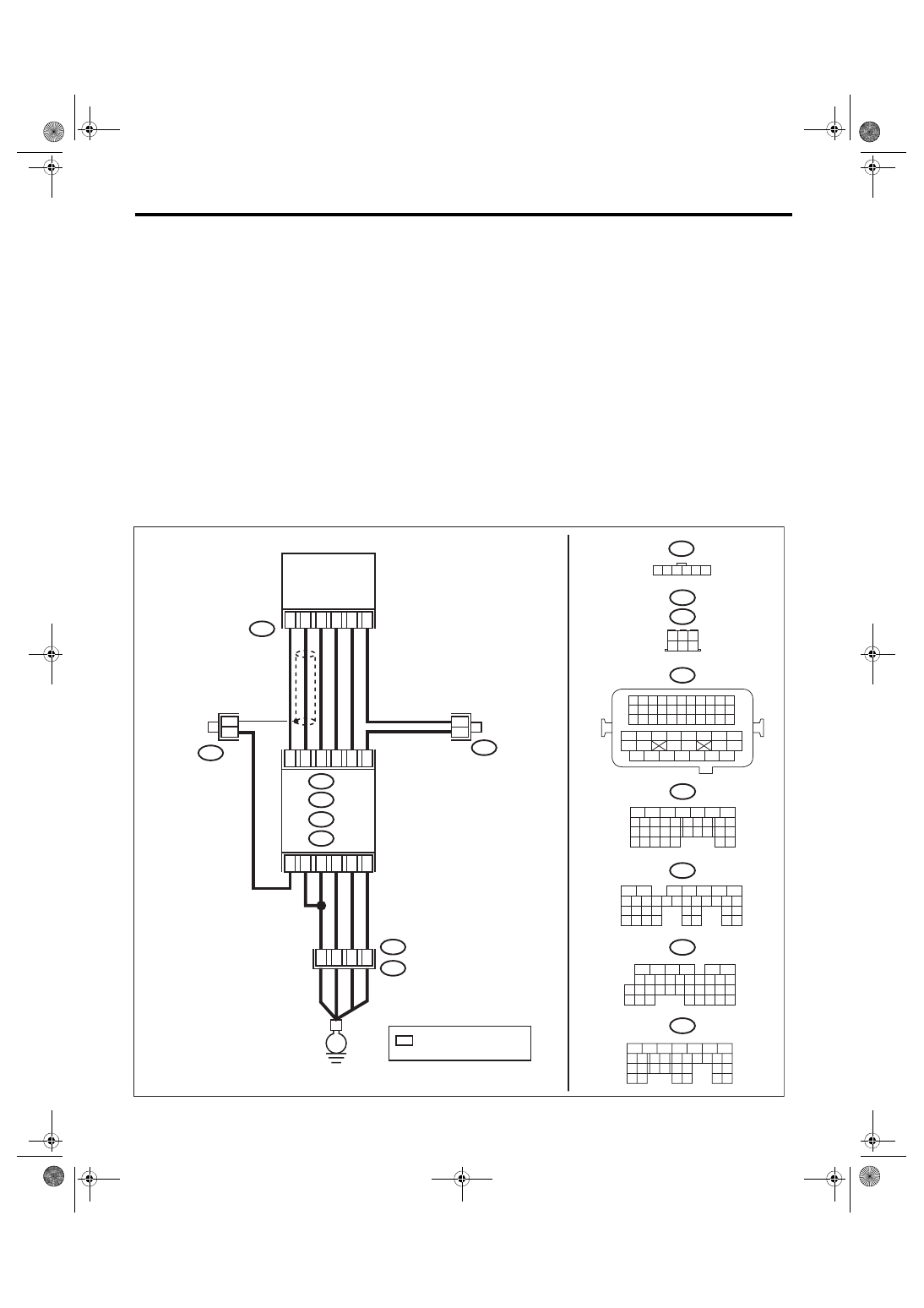
WIRING DIAGRAM:
• Engine electrical system, without SI-DRIVE <Ref. to WI-32, WITHOUT SI-DRIVE, WIRING DIAGRAM,
• Engine electrical system, with SI-DRIVE <Ref. to WI-48, WITH SI-DRIVE, WIRING DIAGRAM, Engine
EN-08749
B315
C: B136
B137
D:
B83
B315
*
*
4
6
5
1
3
2
B21
B23
B29
B22
B31
B30
A4
B21
E2
D1
B21
1 2 3 4
12 13 14 15
5 6 7 8
16 17 18 19
9 10 11
20 21 22
23 24 25 26 27 28 29 30 31 32 33
35
34
37
36
39
38
41
40
43
42
44 45
47
46
49
48
51
50
53
52
54
B137
5
6
7
8
2
1
9
4
3
10
22 23
11 12 13 14 15
24 25
26
16 17
18 19 20 21
27
28 29
30 31
B136
5
6
7 8
2
1
9
4
3
10
24
22 23
25
11 12 13 14 15
26 27
28
16
17 18 19 20 21
33 34
29
32
30
31
35
B135
5
6
7
8
2
1
9
4
3
10
24
22 23
25
11 12 13 14 15
26 27
28
16 17 18 19
20 21
29 30 31
32 33
34 35
B:
C:
D:
B122
B83
A6
C4
D3
B: B135
A: B134
A3
40
34
35
36
B122
1 2 3 4 5 6
*
*
B134
5
6
7
8
2
1
9
4
3
10
24
22 23
25
11 12 13 14 15
26 27
28
16 17
18 19 20 21
33 34
29
32
30 31
A:
*
6
4 5
3
2
1
E
ECM
: TERMINAL No.
OPTIONAL ARRANGEMENT
ACCELERATOR
PEDAL POSITION
SENSOR

EN(H4DOTC)(diag)-386
Diagnostic Procedure with Diagnostic Trouble Code (DTC)
ENGINE (DIAGNOSTICS)
Step
Check
Yes
No
1
CHECK HARNESS BETWEEN ECM AND AC-
CELERATOR PEDAL POSITION SENSOR
CONNECTOR.
1) Turn the ignition switch to OFF.
2) Disconnect the connectors from ECM and
accelerator pedal position sensor.
3) Measure the resistance between ECM con-
nector and chassis ground.
Connector & terminal
(B135) No. 22 — Chassis ground:
(B135) No. 31 — Chassis ground:
Is the resistance 1 MΩ or
more?
Repair the short
circuit to ground in
harness between
ECM connector
and accelerator
pedal position sen-
sor connector.
2
CHECK SHORT CIRCUIT INSIDE THE ECM.
1) Connect the connector to ECM.
2) Measure the resistance between accelera-
tor pedal position sensor connector and chassis
ground.
Connector & terminal
(B315) No. 3 — Chassis ground:
Is the resistance 1 MΩ or
more?
Replace the accel-
erator pedal. <Ref.
to SP(STI)-4,
Accelerator
Pedal.>

EN(H4DOTC)(diag)-387
Diagnostic Procedure with Diagnostic Trouble Code (DTC)
ENGINE (DIAGNOSTICS)
EU:DTC P2128 THROTTLE/PEDAL POSITION SENSOR/SWITCH “E” CIRCUIT
HIGH INPUT
DTC DETECTING CONDITION:
• Immediately at fault recognition
• GENERAL DESCRIPTION <Ref. to GD(H4DOTC)-261, DTC P2128 THROTTLE/PEDAL POSITION
SENSOR/SWITCH “E” CIRCUIT HIGH INPUT, Diagnostic Trouble Code (DTC) Detecting Criteria.>
TROUBLE SYMPTOM:
• Improper idling
• Poor driving performance
CAUTION:
After servicing or replacing faulty parts, perform Clear Memory Mode <Ref. to EN(H4DOTC)(diag)-63,
OPERATION, Clear Memory Mode.>, and Inspection Mode <Ref. to EN(H4DOTC)(diag)-49, PROCE-
WIRING DIAGRAM:
• Engine electrical system, without SI-DRIVE <Ref. to WI-32, WITHOUT SI-DRIVE, WIRING DIAGRAM,
• Engine electrical system, with SI-DRIVE <Ref. to WI-48, WITH SI-DRIVE, WIRING DIAGRAM, Engine
EN-08749
B315
C: B136
B137
D:
B83
B315
*
*
4
6
5
1
3
2
B21
B23
B29
B22
B31
B30
A4
B21
E2
D1
B21
1 2 3 4
12 13 14 15
5 6 7 8
16 17 18 19
9 10 11
20 21 22
23 24 25 26 27 28 29 30 31 32 33
35
34
37
36
39
38
41
40
43
42
44 45
47
46
49
48
51
50
53
52
54
B137
5
6
7
8
2
1
9
4
3
10
22 23
11 12 13 14 15
24 25
26
16 17
18 19 20 21
27
28 29
30 31
B136
5
6
7 8
2
1
9
4
3
10
24
22 23
25
11 12 13 14 15
26 27
28
16
17 18 19 20 21
33 34
29
32
30
31
35
B135
5
6
7
8
2
1
9
4
3
10
24
22 23
25
11 12 13 14 15
26 27
28
16 17 18 19
20 21
29 30 31
32 33
34 35
B:
C:
D:
B122
B83
A6
C4
D3
B: B135
A: B134
A3
40
34
35
36
B122
1 2 3 4 5 6
*
*
B134
5
6
7
8
2
1
9
4
3
10
24
22 23
25
11 12 13 14 15
26 27
28
16 17
18 19 20 21
33 34
29
32
30 31
A:
*
6
4 5
3
2
1
E
ECM
: TERMINAL No.
OPTIONAL ARRANGEMENT
ACCELERATOR
PEDAL POSITION
SENSOR
Нет комментариевНе стесняйтесь поделиться с нами вашим ценным мнением.
Текст