Subaru Impreza 3 / Impreza WRX / Impreza WRX STI. Service manual — part 547
VDC(diag)-87
Diagnostic Procedure with Diagnostic Trouble Code (DTC)
VEHICLE DYNAMICS CONTROL (VDC) (DIAGNOSTICS)
AM:DTC C0071 CHANGE RANGE OF STEERING ANGLE SENSOR IS TOO BIG
DTC DETECTING CONDITION:
Defective steering angle sensor
TROUBLE SYMPTOM:
VDC does not operate.
Step
Check
Yes
No
1
CHECK VDCCM&H/U.
1) Turn the ignition switch to OFF.
2) Connect all connectors.
3) Clear the memory. <Ref. to VDC(diag)-27,
Clear Memory Mode.>
4) Perform the Inspection Mode. <Ref. to
VDC(diag)-26, Inspection Mode.>
5) Read the DTC.
Is the same DTC displayed?
2
CHECK OTHER DTC DETECTION.
Is any other DTC displayed?
Temporary poor
contact occurs.
VDC(diag)-88
Diagnostic Procedure with Diagnostic Trouble Code (DTC)
VEHICLE DYNAMICS CONTROL (VDC) (DIAGNOSTICS)
AN:DTC C0071 STEER ANGLE SENSOR OP
DTC DETECTING CONDITION:
Signal does not come from steering angle sensor.
TROUBLE SYMPTOM:
VDC does not operate.
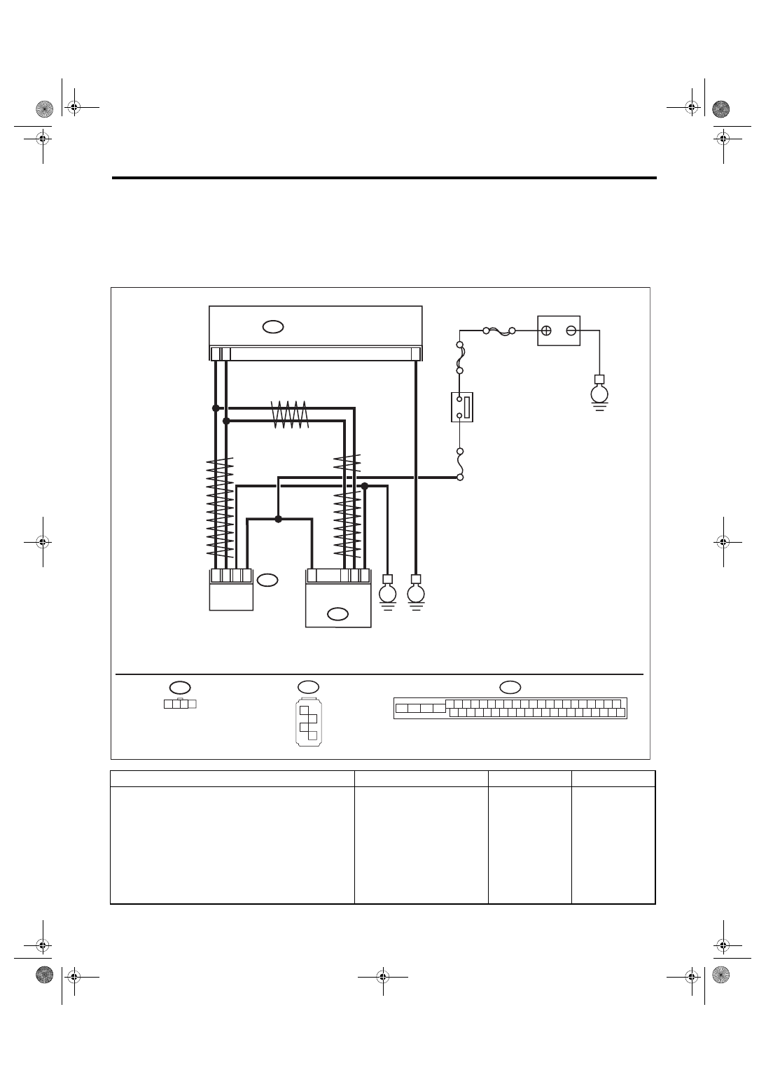
WIRING DIAGRAM:
Vehicle Dynamics Control System <Ref. to WI-67, Vehicle Dynamics Control System.>
Step
Check
Yes
No
1
CHECK POWER SUPPLY FOR STEERING
ANGLE SENSOR.
1) Turn the ignition switch to OFF.
2) Disconnect the connector from steering
angle sensor.
3) Turn the ignition switch to ON.
4) Measure the voltage between steering
angle sensor and chassis ground.
Connector & terminal
(B231) No. 4 (+) — Chassis ground (–):
Is the voltage 10 — 15 V?
Repair the steering
angle sensor
power supply cir-
cuit.
VDC00702
1 2 3 4
B310 VDCCM & H/U
25
10
35
B231
B230
2
4
1
3
1
4
2
3
STEERING
ANGLE
SENSOR
YAW RATE &
G SENSOR
E
B231
SBF-6
MAIN SBF
No.33
E
IGNITION SWITCH
BATTERY
E
B310
4 5 6 7 8 9
26 27 28 29 30
2 3
1
31 32 33 34 35 36
10 11
14 15 16 17 18 19
37 38 39 40
12 13
41 42 43 44 45 46
20 21
23 24
22
25
B230
1
2
3
4
TWISTED P
AIR LINE
TWISTED P
AIR LINE
TWISTED PAIR LINE

VDC(diag)-89
Diagnostic Procedure with Diagnostic Trouble Code (DTC)
VEHICLE DYNAMICS CONTROL (VDC) (DIAGNOSTICS)
2
CHECK GROUND CIRCUIT OF STEERING
ANGLE SENSOR.
Measure the resistance between steering angle
sensor and chassis ground.
Connector & terminal
(B231) No. 3 — Chassis ground:
Is the resistance less than 10
?
Repair ground cir-
cuit in the steering
angle sensor.
3
CHECK STEERING ANGLE SENSOR HAR-
NESS.
1) Disconnect the connector from the
VDCCM&H/U.
2) Measure the resistance between
VDCCM&H/U and steering angel sensor.
Connector & terminal
(B231) No. 1 — (B310) No. 10:
(B231) No. 2 — (B310) No. 35:
Is the resistance less than 1 ? Go to step
Repair the harness
between the steer-
ing angle sensor
and VDCCM&H/U.
4
CHECK GROUND SHORT CIRCUIT OF
STEERING ANGLE SENSOR HARNESS.
Measure the resistance between steering angle
sensor and chassis ground.
Connector & terminal
(B231) No. 1 — Chassis ground:
(B231) No. 2 — Chassis ground:
Is the resistance 10 or more? Go to step
Repair the harness
between the steer-
ing angle sensor
and VDCCM&H/U.
5
CHECK STEERING ANGLE SENSOR.
1) Turn the ignition switch to OFF.
2) Connect all connectors.
3) Clear the memory. <Ref. to VDC(diag)-27,
Clear Memory Mode.>
4) Perform the Inspection Mode. <Ref. to
VDC(diag)-26, Inspection Mode.>
5) Read the DTC.
Is the same DTC displayed?
6
CHECK VDCCM&H/U.
1) Turn the ignition switch to OFF.
2) Replace the steering angle sensor. <Ref. to
VDC-22, Steering Angle Sensor.>
3) Clear the memory. <Ref. to VDC(diag)-27,
Clear Memory Mode.>
4) Perform the Inspection Mode. <Ref. to
VDC(diag)-26, Inspection Mode.>
5) Read the DTC.
Is the same DTC displayed?
7
CHECK OTHER DTC DETECTION.
Is any other DTC displayed?
Temporary poor
contact occurs.
8
CHECK OTHER DTC DETECTION.
Is any other DTC displayed?
Original steering
angle sensor mal-
function
Step
Check
Yes
No
gi14usen005.fm 89 ページ 2013年9月18日 水曜日 午前9時32分
VDC(diag)-90
Diagnostic Procedure with Diagnostic Trouble Code (DTC)
VEHICLE DYNAMICS CONTROL (VDC) (DIAGNOSTICS)
AO:DTC C0071 STEERING ANGLE SENSOR MALFUNCTION
DTC DETECTING CONDITION:
Defective steering angle sensor
TROUBLE SYMPTOM:
• ABS does not operate.
• VDC does not operate.
NOTE:
• Warning light does not illuminate though problem is detected.
• The ABS and VDC operate normally if voltage returns.
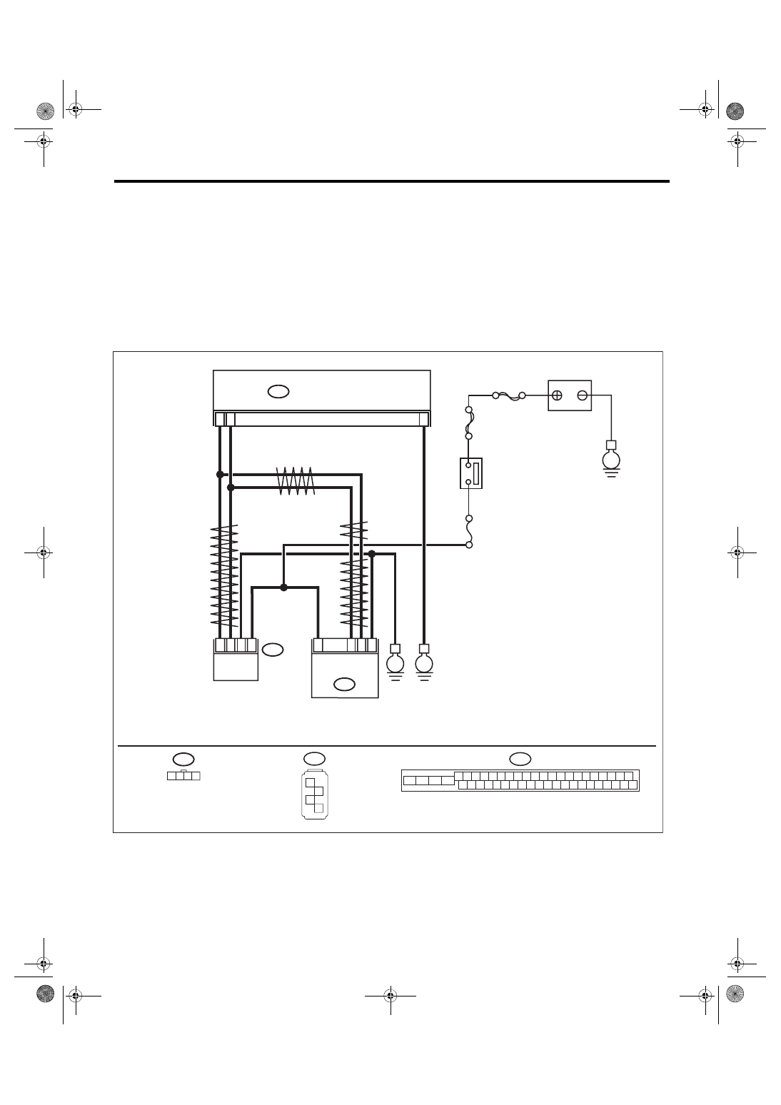
WIRING DIAGRAM:
Vehicle Dynamics Control System <Ref. to WI-67, Vehicle Dynamics Control System.>
VDC00702
1 2 3 4
B310 VDCCM & H/U
25
10
35
B231
B230
2
4
1
3
1
4
2
3
STEERING
ANGLE
SENSOR
YAW RATE &
G SENSOR
E
B231
SBF-6
MAIN SBF
No.33
E
IGNITION SWITCH
BATTERY
E
B310
4 5 6 7 8 9
26 27 28 29 30
2 3
1
31 32 33 34 35 36
10 11
14 15 16 17 18 19
37 38 39 40
12 13
41 42 43 44 45 46
20 21
23 24
22
25
B230
1
2
3
4
TWISTED P
AIR LINE
TWISTED P
AIR LINE
TWISTED PAIR LINE
Нет комментариевНе стесняйтесь поделиться с нами вашим ценным мнением.
Текст