Subaru Impreza 3 / Impreza WRX / Impreza WRX STI. Service manual — part 433
6MT-69
Main Shaft Assembly
MANUAL TRANSMISSION AND DIFFERENTIAL
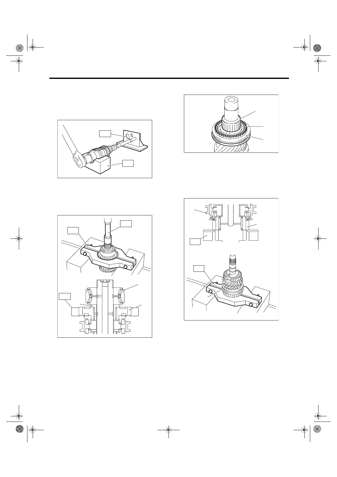
3) Set the main shaft assembly to the ST, and re-
move the lock nut and lock washer.
ST1 18665AA000
HOLDER
ST2 18664AA000
BASE
NOTE:
Use a 38 mm socket wrench.
4) Remove the main shaft assembly from the ST.
5) Set the ST1 to the 6th drive gear, and use a
press to remove the double taper roller bearing,
bushing and 6th drive gear.
ST1 18722AA010
REMOVER
ST2 899864100
REMOVER
6) Remove the 5th-6th sleeve, 6th needle bearing
and 6th baulk ring.
7) Set the ST to the 3rd drive gear, and use a press
to remove individual parts.
ST 18720AA000 REMOVER
(A) Double taper roller bearing
(B) Bushing
(C) 6th drive gear
MT-00556
ST2
ST1
MT-00557
(A)
(B)
(C)
ST1
ST2
ST1
(A) Needle bearing
(B) 6th baulk ring
(C) 5th-6th sleeve
(A) 3rd drive gear
(B) 3rd-4th sleeve
(A)
(B)
(C)
MT-00558
(A)
ST
(B)
(B)
ST
MT-01406
6MT-70
Main Shaft Assembly
MANUAL TRANSMISSION AND DIFFERENTIAL
D: ASSEMBLY
NOTE:
When replacing the following parts, replace as a
set.
• Sleeve and hub
• Outer baulk ring, 3rd synchro cone and inner
baulk ring
• Double taper roller bearing
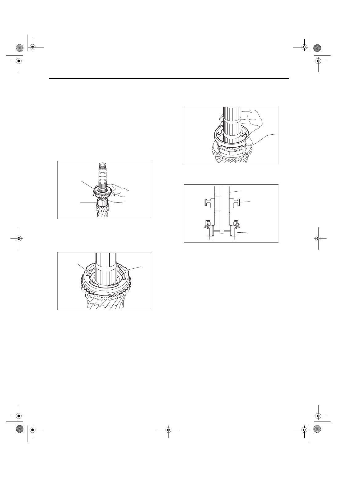
1) Apply adequate transmission gear oil to the main
shaft, 3rd needle bearing and 3rd drive gear inner
surface.
2) Install the 3rd needle bearing and 3rd drive gear
to the main shaft.
3) Install the inner baulk ring, 3rd synchro cone and
outer baulk ring.
NOTE:
Install the 3rd synchro cone by aligning the protru-
sion of the 3rd synchro cone with the hole on the
3rd drive gear.
4) Install the 3rd-4th hub and 4th bushing.
(1) Being careful of the install direction of the
3rd-4th hub, set to the main shaft.
(A) 3rd drive gear
(B) 3rd needle bearing
(A) Inner baulk ring
(B) Outer baulk ring
MT-00560
(A)
(B)
(A)
(B)
MT-00561
(A) Main shaft
(B) 3rd-4th hub
(C) 3rd drive gear
MT-01501
MT-00884
(A)
(B)
(C)
6MT-71
Main Shaft Assembly
MANUAL TRANSMISSION AND DIFFERENTIAL
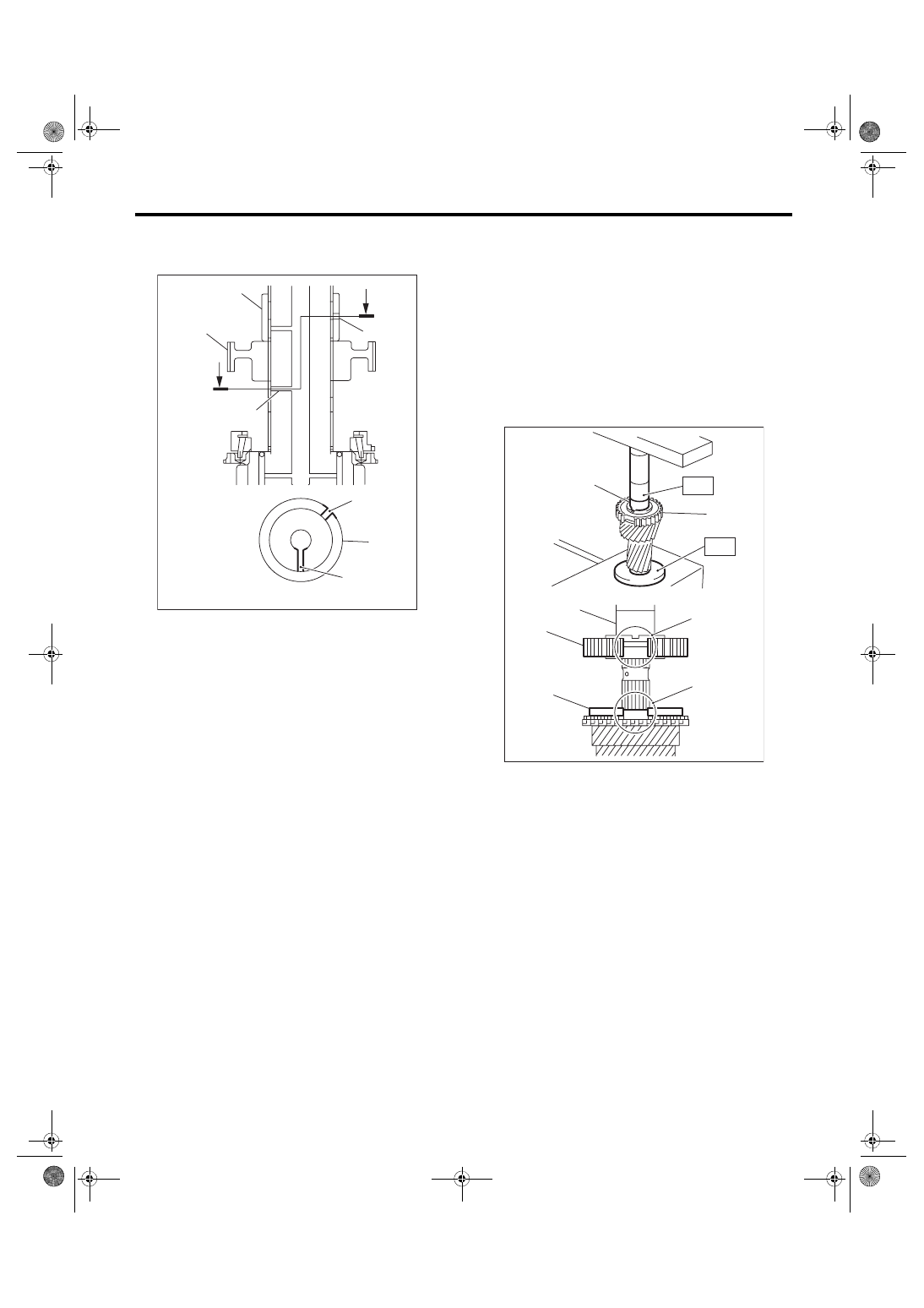
(2) With the main shaft oil hole and 4th bushing
oil hole out of alignment, attach to the main
shaft.
(3) Using the ST, push in to the 3rd-4th hub and
4th bushing all at once.
ST1 18651AA000
INSTALLER
ST2 398177700
INSTALLER
CAUTION:
Do not apply pressure in excess of 40 kN (4.0
ton, 4.4 US ton, 3.9 Imp ton).
NOTE:
When pushing into the 3rd-4th hub and 4th bush-
ing, move the outer baulk ring to match the protru-
sion of the outer baulk ring and the cut out on the
3rd-4th bushing.
5) Make sure that the 3rd drive gear can be turned
smoothly by hand. If it does not turn smoothly, re-
assemble.
(A) 4th bushing
(B) 3rd-4th hub
(C) 4th bushing oil hole
(D) Main shaft oil hole
MT-01819
(A)
(B)
A
(D)
(C)
A
A - A
(C)
(D)
(A)
(A) 3rd-4th hub
(B) Outer baulk ring
(C) Cut out on the 3rd-4th hub
(D) Protrusion of the outer baulk ring
(E) 4th bushing
MT-00555
(D)
(C)
(A)
(E)
(E)
(A)
(B)
ST1
ST2
6MT-72
Main Shaft Assembly
MANUAL TRANSMISSION AND DIFFERENTIAL
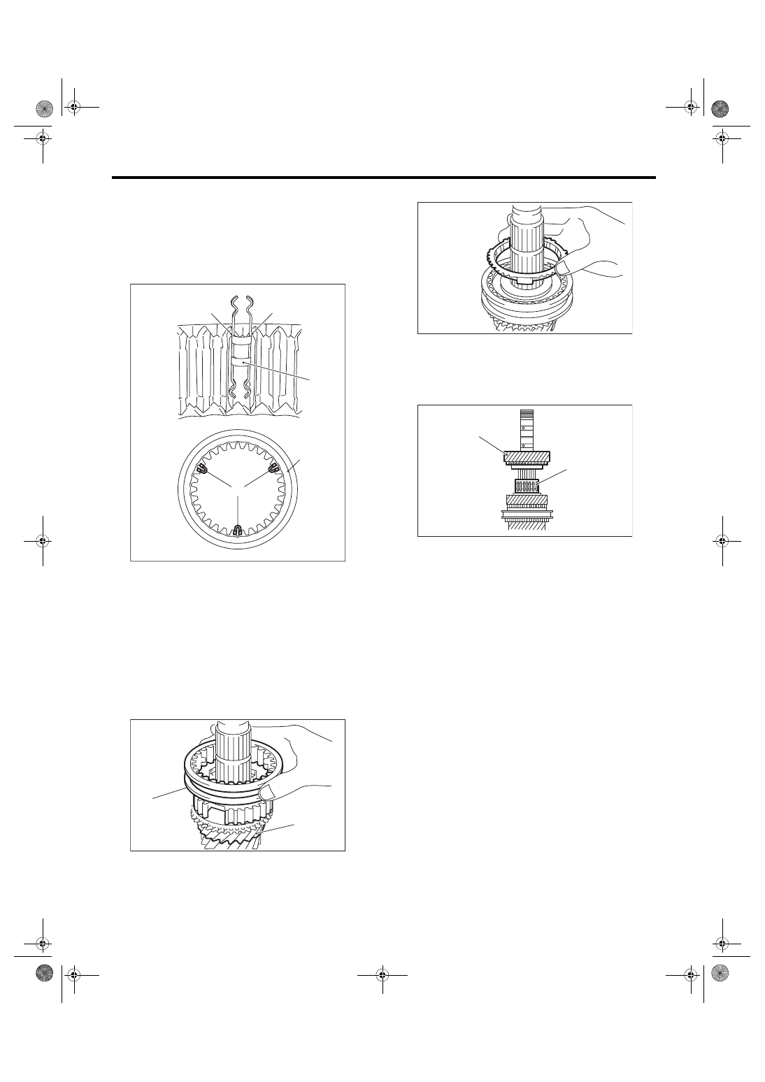
6) Attach the 3rd-4th shifting insert key at the ap-
propriate position of the 3rd-4th sleeve.
NOTE:
• The location angle of each shifting insert key is
120°.
• Refer to the following figure to install the shifting
insert key.
7) Attach the 3rd-4th sleeve to the 3rd-4th hub.
NOTE:
• There is an identification groove on the 3rd-4th
sleeve.
• Place the groove towards the 3rd drive gear, and
attach the 3rd-4th sleeve.
8) Install the 4th baulk ring.
9) Apply adequate transmission gear oil to the main
shaft, 4th needle bearing and 4th drive gear inner
surface.
10) Install the 4th needle bearing and 4th drive
gear.
(A) Attach the straight part of the shifting insert key
to the sleeve convex portion.
(B) 3rd-4th shifting insert key
(C) 3rd-4th sleeve
(A) 3rd drive gear
(B) 3rd-4th sleeve identification groove (1)
(B)
(C)
MT-01820
(A)
(B)
(A)
MT-00563
(A)
(B)
(A) 4th needle bearing
(B) 4th drive gear
MT-00564
MT-00565
(A)
(B)
Нет комментариевНе стесняйтесь поделиться с нами вашим ценным мнением.
Текст