Subaru Impreza 3 / Impreza WRX / Impreza WRX STI. Service manual — part 131
FU(w/o STI)-51
Wastegate Control Solenoid Valve
FUEL INJECTION (FUEL SYSTEMS)
15.Wastegate Control Solenoid
Valve
A: REMOVAL
1) Remove the collector cover.
2) Disconnect the ground cable from battery.
3) Disconnect the connector (A) from the waste-
gate control solenoid valve.
4) Disconnect the vacuum hose (B) and air control
hose (C) from the wastegate control solenoid valve.
5) Remove the wastegate control solenoid valve
from the bracket.
B: INSTALLATION
Install in the reverse order of removal.
Tightening torque:
6.4 N·m (0.7 kgf-m, 4.7 ft-lb)
C: INSPECTION
1. WASTEGATE CONTROL SOLENOID
VALVE
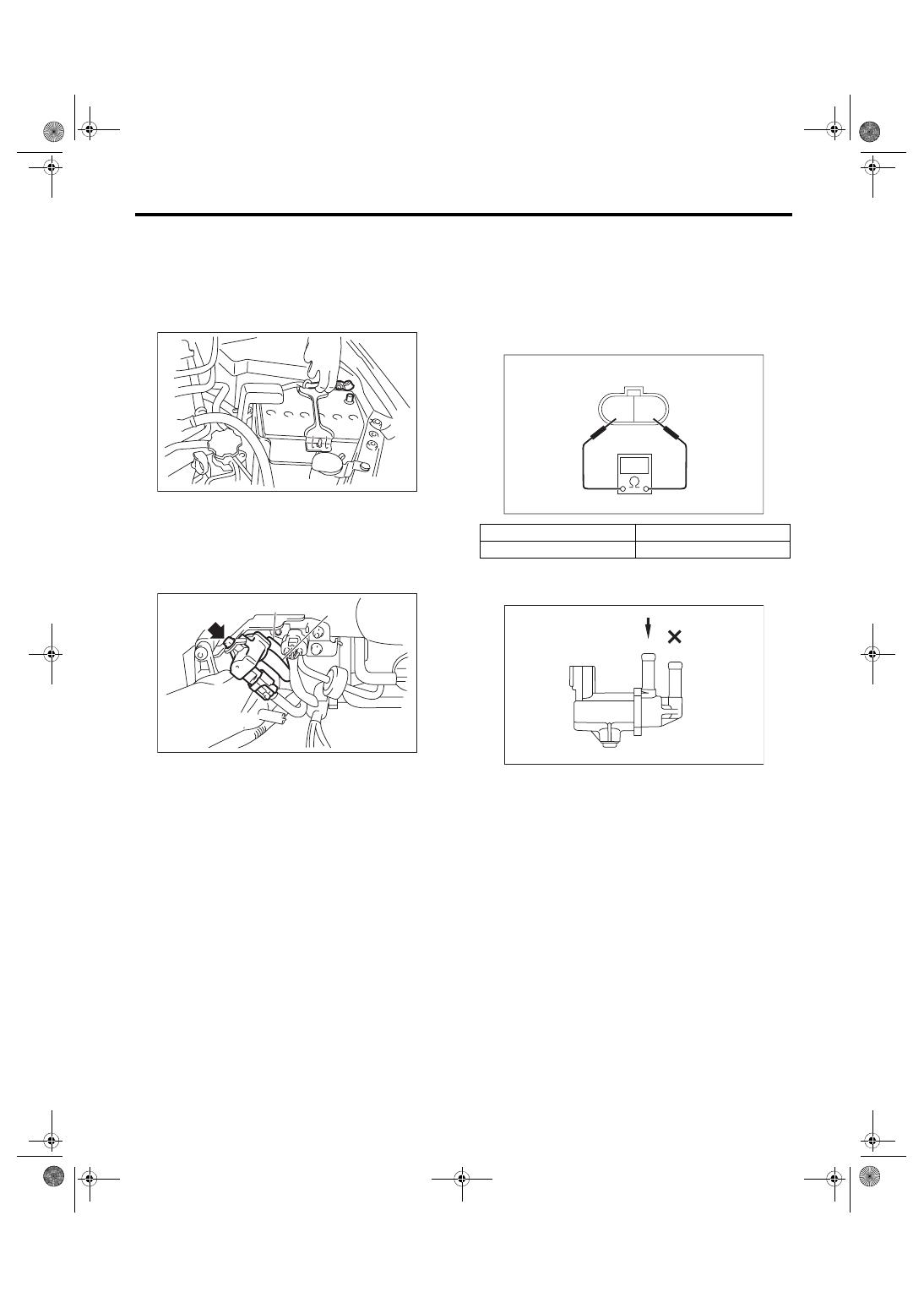
1) Check that the wastegate control solenoid valve
has no deformation, cracks or other damages.
2) Check the resistance between the wastegate
control solenoid valve terminals.
3) Check that air does not come out from (B) when
air is blown into (A).
IN-00203
FU-05739
(C)
(A)
(B)
Terminal No.
Standard
1 and 2
28±2 Ω (when 20°C (68°F))
2 1
EC-02426
FU-04069
(A)
(B)
FU(w/o STI)-52
Wastegate Control Solenoid Valve
FUEL INJECTION (FUEL SYSTEMS)
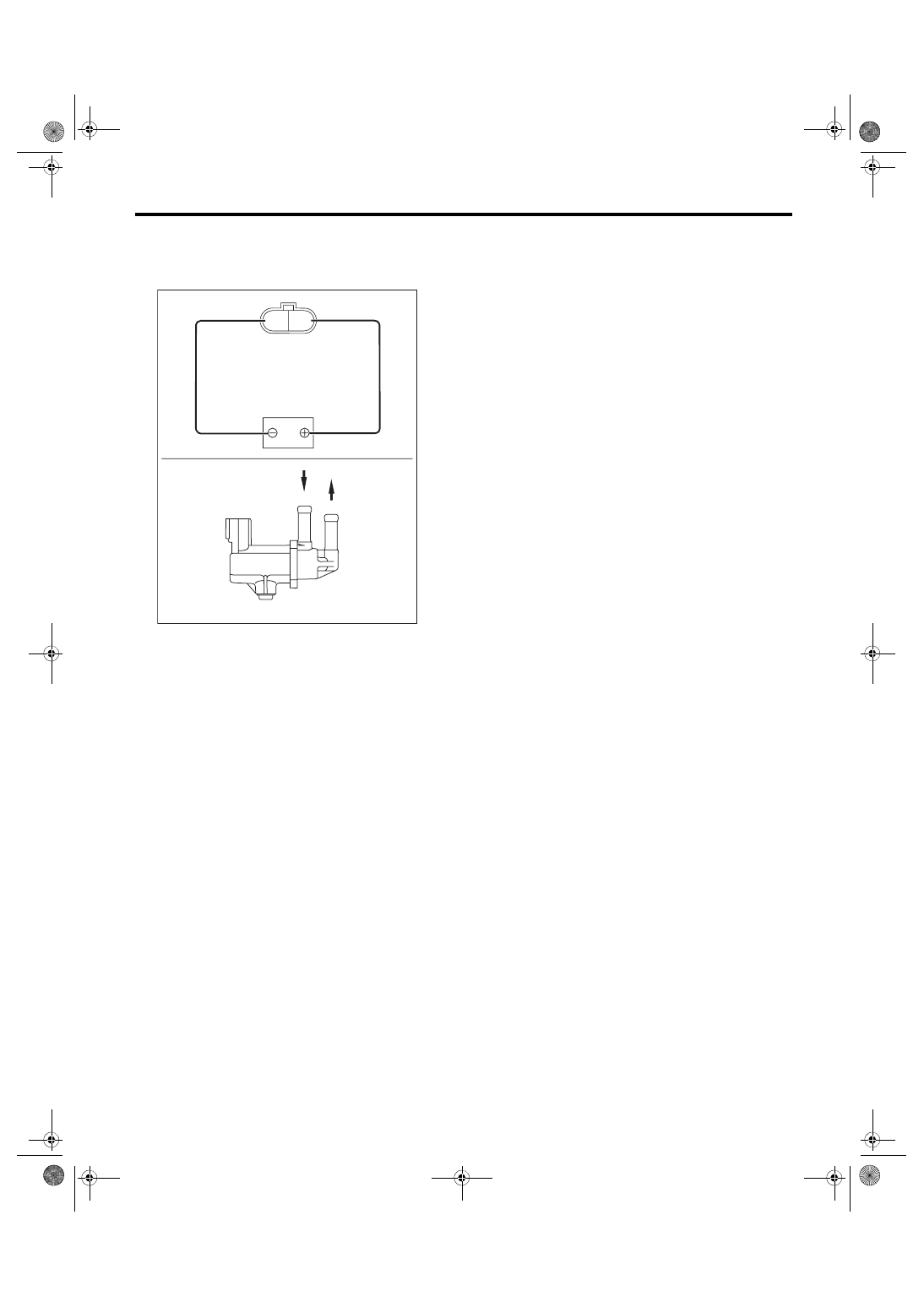
4) Connect the battery positive terminal to the ter-
minal No. 1 and the battery negative terminal to the
terminal No. 2. Check that air is discharged from
(B), when supplying air to (A).
2. OTHER INSPECTIONS
Check that the vacuum hose and air control hose
have no cracks, damage or loose part.
FU-04070
2 1
(A)
(B)
FU(w/o STI)-53
Front Oxygen (A/F) Sensor
FUEL INJECTION (FUEL SYSTEMS)
16.Front Oxygen (A/F) Sensor
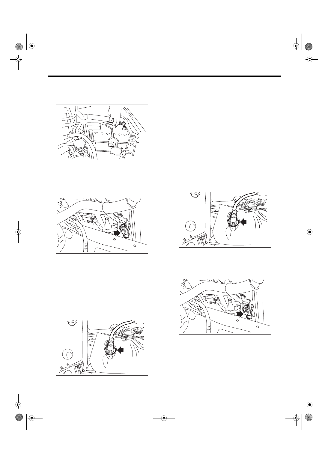
A: REMOVAL
1) Disconnect the ground cable from battery.
2) Remove the air intake duct (rear) and air cleaner
case. <Ref. to IN(w/o STI)-10, REMOVAL, Air In-
take Duct.> <Ref. to IN(w/o STI)-8, REMOVAL, Air
3) Disconnect the connectors from front oxygen (A/F)
sensor.
4) Lift up the vehicle.
5) Remove the under cover. <Ref. to EI-28, RE-
6) Apply spray-type lubricant to the threaded por-
tion of front oxygen (A/F) sensor, and leave it for
one minute or more.
7) Remove the front oxygen (A/F) sensor.
CAUTION:
When removing the front oxygen (A/F) sensor,
wait until exhaust pipe cools, otherwise it will
damage the exhaust pipe.
B: INSTALLATION
CAUTION:
If lubricant is spilt onto the exhaust pipe, wipe it
off completely with cloth to avoid emission of
smoke or causing a fire.
1) Before installing front oxygen (A/F) sensor, ap-
ply anti-seize compound only to the threaded por-
tion of front oxygen (A/F) sensor to make the next
removal easier.
CAUTION:
Never apply anti-seize compound to the protec-
tor of front oxygen (A/F) sensor.
Anti-seize compound:
NEVER-SEEZ NSN, JET LUBE SS-30 or
equivalent
2) Install the front oxygen (A/F) sensor.
Tightening torque:
30 N·m (3.1 kgf-m, 22.1 ft-lb)
3) Install the under cover. <Ref. to EI-28, INSTAL-
4) Lower the vehicle.
5) Connect the connector of front oxygen (A/F)
sensor.
6) Install the air intake duct (rear) and air cleaner
case. <Ref. to IN(w/o STI)-8, INSTALLATION, Air
Cleaner Case.> <Ref. to IN(w/o STI)-10, INSTAL-
IN-00203
FU-05717
FU-04624
FU-04624
FU-05717
FU(w/o STI)-54
Front Oxygen (A/F) Sensor
FUEL INJECTION (FUEL SYSTEMS)
7) Connect the battery ground terminal.
C: INSPECTION
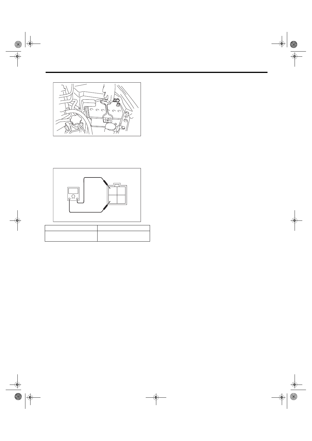
1) Check that the front oxygen (A/F) sensor has no
deformation, cracks or other damages.
2) Measure the resistance between front oxygen
(A/F) sensor terminals.
Terminal No.
Standard
2 and 4
2.4±0.24 Ω
(when 20°C (68°F))
IN-00203
2 1
4 3
FU-05147
Нет комментариевНе стесняйтесь поделиться с нами вашим ценным мнением.
Текст