Subaru Impreza 3 / Impreza WRX / Impreza WRX STI. Service manual — part 132
FU(w/o STI)-55
Rear Oxygen Sensor
FUEL INJECTION (FUEL SYSTEMS)
17.Rear Oxygen Sensor
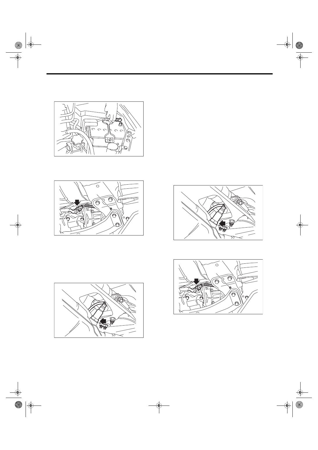
A: REMOVAL
1) Disconnect the ground cable from battery.
2) Lift up the vehicle.
3) Disconnect the connector from the rear oxygen
sensor, and remove the clip (A) holding the rear ox-
ygen sensor harness.
4) Apply spray-type lubricant to the threaded por-
tion of rear oxygen sensor, and leave it for one
minute or more.
5) Remove the rear oxygen sensor.
CAUTION:
When removing the rear oxygen sensor, wait
until exhaust pipe cools, otherwise it will dam-
age the exhaust pipe.
B: INSTALLATION
CAUTION:
If lubricant is spilt onto the exhaust pipe, wipe it
off completely with cloth to avoid emission of
smoke or causing a fire.
1) Before installing rear oxygen sensor, apply the
anti-seize compound only to the threaded portion of
rear oxygen sensor to make the next removal eas-
ier.
CAUTION:
Never apply anti-seize compound to the protec-
tor of rear oxygen sensor.
Anti-seize compound:
NEVER-SEEZ NSN, JET LUBE SS-30 or
equivalent
2) Install the rear oxygen sensor.
Tightening torque:
21 N·m (2.1 kgf-m, 15.5 ft-lb)
3) Connect the connector to the rear oxygen sen-
sor, and hold the rear oxygen sensor harness with
the clip (A).
4) Lower the vehicle.
IN-00203
FU-04637
(A)
FU-04626
FU-04626
FU-04637
(A)
FU(w/o STI)-56
Rear Oxygen Sensor
FUEL INJECTION (FUEL SYSTEMS)
5) Connect the battery ground terminal.
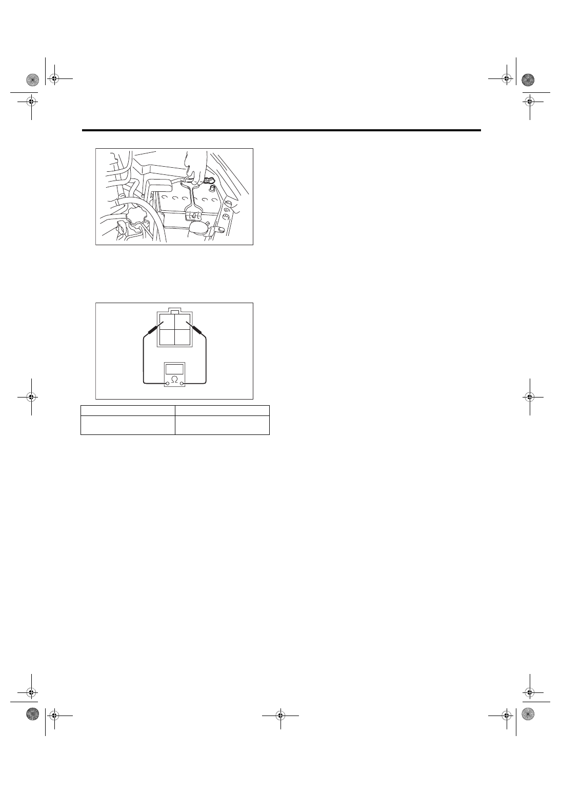
C: INSPECTION
1) Check that the rear oxygen sensor has no defor-
mation, cracks or other damages.
2) Measure the resistance between rear oxygen
sensor terminals.
Terminal No.
Standard
1 and 2
5.6
+0.8
–0.6
Ω
(when 20°C (68°F))
IN-00203
2 1
4 3
FU-04073
FU(w/o STI)-57
Engine Control Module (ECM)
FUEL INJECTION (FUEL SYSTEMS)
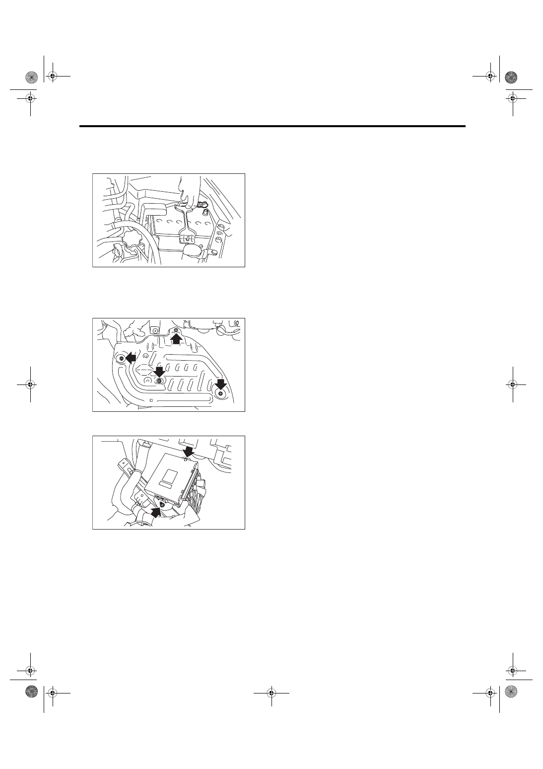
18.Engine Control Module (ECM)
A: REMOVAL
1) Disconnect the ground cable from battery.
2) Remove the lower inner trim of passenger’s
side. <Ref. to EI-57, REMOVAL, Lower Inner
3) Turn over the floor mat of passenger’s seat.
4) Remove the protect cover.
5) Remove the nuts and bolts which hold the ECM
to the bracket.
6) Disconnect the ECM connectors, and take out
the ECM.
B: INSTALLATION
Install in the reverse order of removal.
CAUTION:
• When the ECM of model with immobilizer has
been replaced, be sure to perform the registra-
tion of immobilizer system. (Refer to “PC appli-
cation help for Subaru Select Monitor”.)
• If replacing ECM or the bracket, replace both
parts with new parts at a time.
• After installing the bracket to ECM, do not
separate the bracket.
• If the bracket has been installed to ECM in the
wrong direction, replace both parts to new
parts.
NOTE:
When replacing the ECM, be careful not to use the
wrong spec. ECM to avoid any damage on the fuel
injection system.
Tightening torque:
7.5 N·m (0.8 kgf-m, 5.5 ft-lb)
C: INSPECTION
Check that the ECM has no deformation, cracks or
other damages.
IN-00203
FU-03416
FU-03417
FU(w/o STI)-58
Main Relay
FUEL INJECTION (FUEL SYSTEMS)
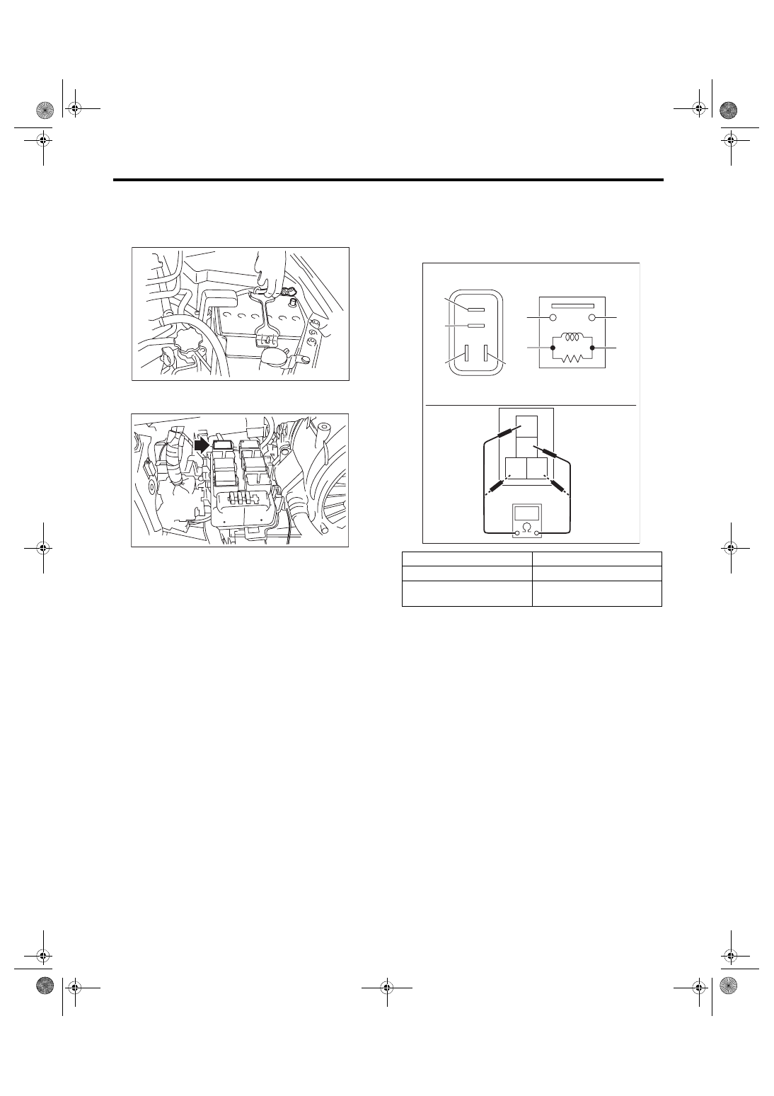
19.Main Relay
A: REMOVAL
1) Disconnect the ground cable from battery.
2) Remove the main relay from the relay block on
the back side of the glove box.
B: INSTALLATION
Install in the reverse order of removal.
C: INSPECTION
1) Check that the main relay has no deformation,
cracks or other damages.
2) Measure the resistance between main relay ter-
minals.
IN-00203
FU-03418
Terminal No.
Standard
1 and 2
1 MΩ or more
3 and 4
130.4 — 230.8 Ω
(when 20°C (68°F))
1
2
3 4
(1)
(2)
(1)
(4)
(2)
(3)
(3)
(4)
IN-02836
Нет комментариевНе стесняйтесь поделиться с нами вашим ценным мнением.
Текст