Subaru Impreza 3 / Impreza WRX / Impreza WRX STI. Service manual — part 604
AC(diag)-21
Diagnostics for A/C System Malfunction
HVAC SYSTEM (AUTO A/C) (DIAGNOSTICS)
8
CHECK HARNESS BETWEEN AUTO A/C
CONTROL MODULE AND ECM.
1) Turn the ignition switch to OFF.
2) Disconnect the harness connector of auto
A/C control module and ECM.
3) Measure the resistance of harness between
auto A/C control module connector and ECM
connector.
Connector & terminal
(i88) No. 36 — (B136) No. 29:
Is the resistance less than 1 Ω? Go to step
Repair the har-
ness.
9
CHECK MAGNET CLUTCH ON SIGNAL.
1) Stop the engine and turn the A/C switch to
OFF.
2) Turn the ignition switch to ON.
3) Measure the voltage between ECM connec-
tor terminal and chassis ground.
Connector & terminal
(B135) No. 35 (+) — Chassis ground (–):
Is the voltage 10 V or more?
Check for open or
short circuit in the
harness between
A/C relay and
ECM.
10
CHECK MAGNET CLUTCH ON SIGNAL.
1) Start the engine and turn the A/C switch to
ON.
2) Turn the temperature control dial at maxi-
mum cool position.
3) Measure the voltage between ECM connec-
tor terminal and chassis ground.
Connector & terminal
(B135) No. 35 (+) — Chassis ground (–):
Is the voltage 0 V?
11
CHECK POWER SUPPLY FOR MAGNET
CLUTCH.
1) Stop the engine and turn the A/C switch to
OFF.
2) Disconnect the harness connector of mag-
net clutch.
3) Start the engine and turn the A/C switch to
ON.
4) Turn the temperature control dial at maxi-
mum cool position.
5) Measure the voltage between magnet
clutch harness connector terminal and chassis
ground.
Connector & terminal
(F24) No. 1 (+) — Chassis ground (–):
Is the voltage 10 V or more?
Inspect the com-
pressor. <Ref. to
AC-33, INSPEC-
TION, Compres-
sor.>
Check for open or
short circuit in the
harness between
A/C relay and mag-
net clutch.
Step
Check
Yes
No
AC(diag)-22
Diagnostics for A/C System Malfunction
HVAC SYSTEM (AUTO A/C) (DIAGNOSTICS)
E: FRESH/RECIRC SWITCH LIGHT IS BLINKING
TROUBLE SYMPTOM:
FRESH/RECIRC switch indicator blinks when the ignition switch is turned from OFF to ON.
NOTE:
When the ignition switch is turned from OFF to ON immediately after the reconnection of the battery or when
the battery power supply voltage is low (battery voltage: 9 V or less), the indicator may blink. Throughout this
blinking period, the system recognizes the specified position of the air mix door actuator and mode door ac-
tuator. So, this is not a malfunction. (Number of blinking: 8 — 9 at 0.5 second intervals)
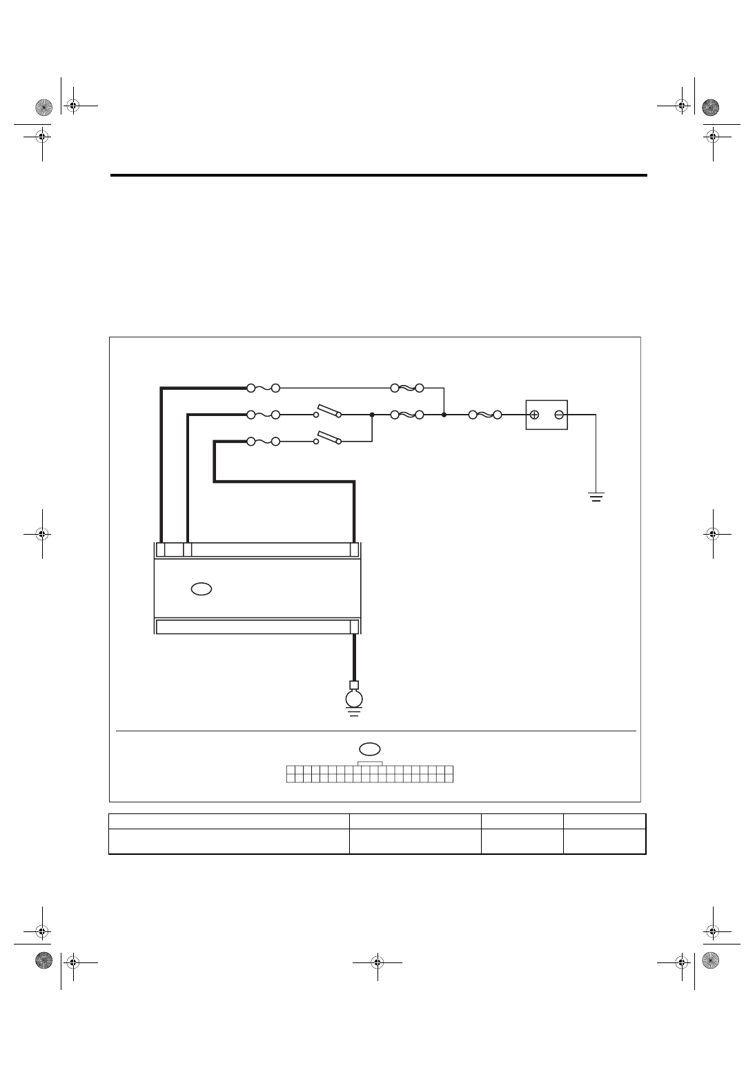
WIRING DIAGRAM:
Air conditioning system, auto A/C model <Ref. to WI-77, AUTO A/C MODEL, WIRING DIAGRAM, Air Con-
Step
Check
Yes
No
1
CHECK INDICATOR BLINKING.
Turn the ignition switch to ON.
Does the indicator blink?
System is normal.
i88
1 2 3 4 5 6 7 8 9 10 11 12 13 14 15 16 17 18 19 20
21 22 23 24 25 26 27 28 29 30 31 32 33 34 35 36 37 38 39 40
i88
31
15
34
32
SBF-8
E
SBF-6
AC-02426
ACC
MAIN SBF
F/B No. 7
F/B No. 22
F/B No. 31
IGNITION SWITCH
BATTERY
AUTO A/C CONTROL MODULE
AC(diag)-23
Diagnostics for A/C System Malfunction
HVAC SYSTEM (AUTO A/C) (DIAGNOSTICS)
2
CHECK INDICATOR BLINKING.
1) Turn the ignition switch to OFF and wait for 3
minutes.
2) Turn the ignition switch to ON again.
Does the indicator blink?
System is normal.
3
CHECK AUTO A/C CONTROL MODULE
POWER CIRCUIT.
1) Turn the ignition switch to OFF.
2) Disconnect the auto A/C control module
harness connector.
3) Measure the voltage between auto A/C con-
trol module and chassis ground after turning the
ignition switch to the ON position.
Connector & terminal
(i88) No. 31 (+) — Chassis ground (–):
Is the voltage 9 V or less?
Check the harness
for open or short
circuit. Check the
battery condition.
System is normal.
Step
Check
Yes
No
AC(diag)-24
Diagnostic Procedure for Actuators
HVAC SYSTEM (AUTO A/C) (DIAGNOSTICS)
7. Diagnostic Procedure for Actuators
A: INTAKE DOOR ACTUATOR
TROUBLE SYMPTOM:
FRESH/RECIRC mode is not changed.
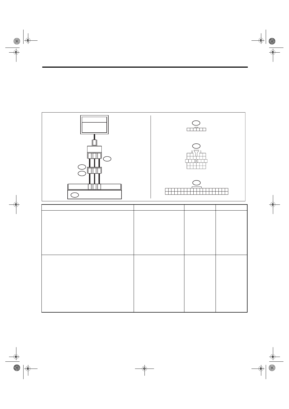
WIRING DIAGRAM:
Air conditioning system, auto A/C model <Ref. to WI-77, AUTO A/C MODEL, WIRING DIAGRAM, Air Con-
Step
Check
Yes
No
1
CHECK POWER SUPPLY FOR INTAKE
DOOR ACTUATOR.
1) Turn the ignition switch to OFF.
2) Disconnect the intake door actuator con-
nector.
3) Turn the ignition switch to ON.
4) Measure the voltage between intake door
actuator connector and chassis ground.
Connector & terminal
(B163) No. 1 (+) — Chassis ground (–):
Is the voltage approx. 10 V or
more?
Check for open or
short circuit in the
harness between
intake door actua-
tor and fuse.
2
CHECK HARNESS BETWEEN AUTO A/C
CONTROL MODULE AND INTAKE DOOR
ACTUATOR.
1) Turn the ignition switch to OFF.
2) Disconnect the auto A/C control module
connector.
3) Measure the resistance between intake
door actuator connector and auto A/C control
module connector.
Connector & terminal
(i88) No. 8 — (B163) No. 6:
(i88) No. 7 — (B163) No. 5:
(i88) No. 6 — (B163) No. 4:
Is the resistance less than 1 Ω? Go to step
Repair the harness
between auto A/C
control module and
intake door actua-
tor.
21
20
19
18
17
16
15
14
13
12
11
28
26 27
25
23
22
24
10
3 4
9
1 2
8
7
6
5
i1
8
26
7
1 2 3 4 5 6
B163
i1
B36
i88
1 2 3 4 5 6 7 8 9 10 11 12 13 14 15 16 17 18 19 20
21 22 23 24 25 26 27 28 29 30 31 32 33 34 35 36 37 38 39 40
6
8
1
4
5
B163
6
7
i88
AC-02428
AUTO A/C CONTROL MODULE
TO POWER
SUPPLY CIRCUIT
FB-46
F/B FUSE NO. 22
(IG)
INTAKE DOOR
ACTUATOR
Нет комментариевНе стесняйтесь поделиться с нами вашим ценным мнением.
Текст