Subaru Impreza 3 / Impreza WRX / Impreza WRX STI. Service manual — part 605
AC(diag)-25
Diagnostic Procedure for Actuators
HVAC SYSTEM (AUTO A/C) (DIAGNOSTICS)
B: MODE DOOR ACTUATOR
TROUBLE SYMPTOM:
Air flow outlet is not changed.
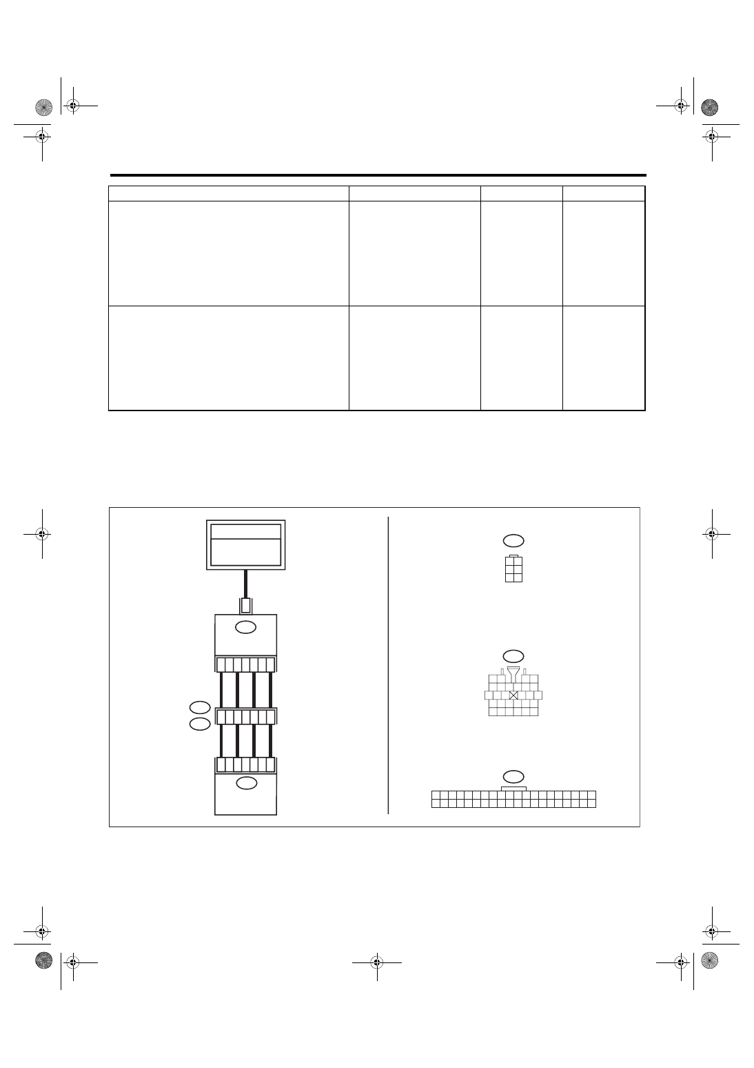
WIRING DIAGRAM:
Air conditioning system, auto A/C model <Ref. to WI-77, AUTO A/C MODEL, WIRING DIAGRAM, Air Con-
3
CHECK OPERATION OF INTAKE DOOR AC-
TUATOR.
1) Connect the intake door actuator connector.
2) Ground the auto A/C control module con-
nector with a suitable wire.
3) Turn the ignition switch to ON, and check the
operation of intake door actuator.
Connector & terminal
(i88) No. 6 — Chassis ground:
Does the actuator move to the
FRESH side?
Replace the intake
door actuator.
4
CHECK OPERATION OF INTAKE DOOR AC-
TUATOR.
1) Turn the ignition switch to OFF.
2) Ground the auto A/C control module con-
nector with a suitable wire.
3) Turn the ignition switch to ON, and check the
operation of intake door actuator.
Connector & terminal:
(i88) No. 8 — Chassis ground:
Does the actuator move to the
RECIRC side?
Replace the auto
A/C control mod-
ule. <Ref. to AC-
31, REMOVAL,
Control Unit (Auto
A/C Model).>
Replace the intake
door actuator.
Step
Check
Yes
No
i1
5 6 7 8
2
1
9
4
3
10
24
22
23
25
27
26
28
11 12 13
14 15 16
17 18 19 20 21
25
20
22
21
2
5
1
6
B77
4
3
2
1
i88
3
i1
B36
B77
1 2
3 4
5 6
i88
1 2 3 4 5 6 7 8 9 10 11 12 13 14 15 16 17 18 19 20
21 22 23 24 25 26 27 28 29 30 31 32 33 34 35 36 37 38 39 40
AC-02429
TO POWER
SUPPLY CIRCUIT
FB-18
F/B FUSE NO. 7
(B)
AUTO A/C
CONTROL
MODULE
MODE DOOR
ACTUATOR
AC(diag)-26
Diagnostic Procedure for Actuators
HVAC SYSTEM (AUTO A/C) (DIAGNOSTICS)
Step
Check
Yes
No
1
CHECK POWER SUPPLY FOR MODE DOOR
ACTUATOR.
1) Turn the ignition switch to OFF.
2) Disconnect the mode door actuator connec-
tor.
3) Turn the ignition switch to ON.
4) Measure the voltage between the mode
door actuator connector terminal and chassis
ground.
Connector & terminal
(B77) No. 3 (+) — Chassis ground (–):
Is the voltage approx. 10 V or
more?
Check the DC
power supply cir-
cuit.
2
CHECK MODE DOOR ACTUATOR.
1) Turn the ignition switch to OFF.
2) Measure the resistance between mode door
actuator terminals using a tester.
Connector & terminal
(B77) No. 3 — No. 1:
(B77) No. 3 — No. 2:
(B77) No. 3 — No. 5:
(B77) No. 3 — No. 6:
Is the resistance 80 — 100 Ω? Go to step
Replace the mode
door actuator.
3
CHECK HARNESS BETWEEN AUTO A/C
CONTROL MODULE AND MODE DOOR AC-
TUATOR.
1) Disconnect the auto A/C control module
connector.
2) Measure the resistance between auto A/C
control module and mode door actuator con-
nector.
Connector & terminal
(B77) No. 1 — (i88) No. 4:
(B77) No. 2 — (i88) No. 3:
(B77) No. 5 — (i88) No. 2:
(B77) No. 6 — (i88) No. 1:
Is the resistance less than 1 Ω? Go to step
Repair the harness
between auto A/C
control module and
mode door actua-
tor.
4
CHECK FOR POOR CONTACT.
Check poor contact of auto A/C control module
and connector.
Is there poor contact of connec-
tor?
Repair the connec-
tor.
Replace the auto
A/C control mod-
ule. <Ref. to AC-
31, REMOVAL,
Control Unit (Auto
A/C Model).>
AC(diag)-27
Diagnostic Procedure for Actuators
HVAC SYSTEM (AUTO A/C) (DIAGNOSTICS)
C: AIR MIX DOOR ACTUATOR
TROUBLE SYMPTOM:
Outlet air temperature does not change.
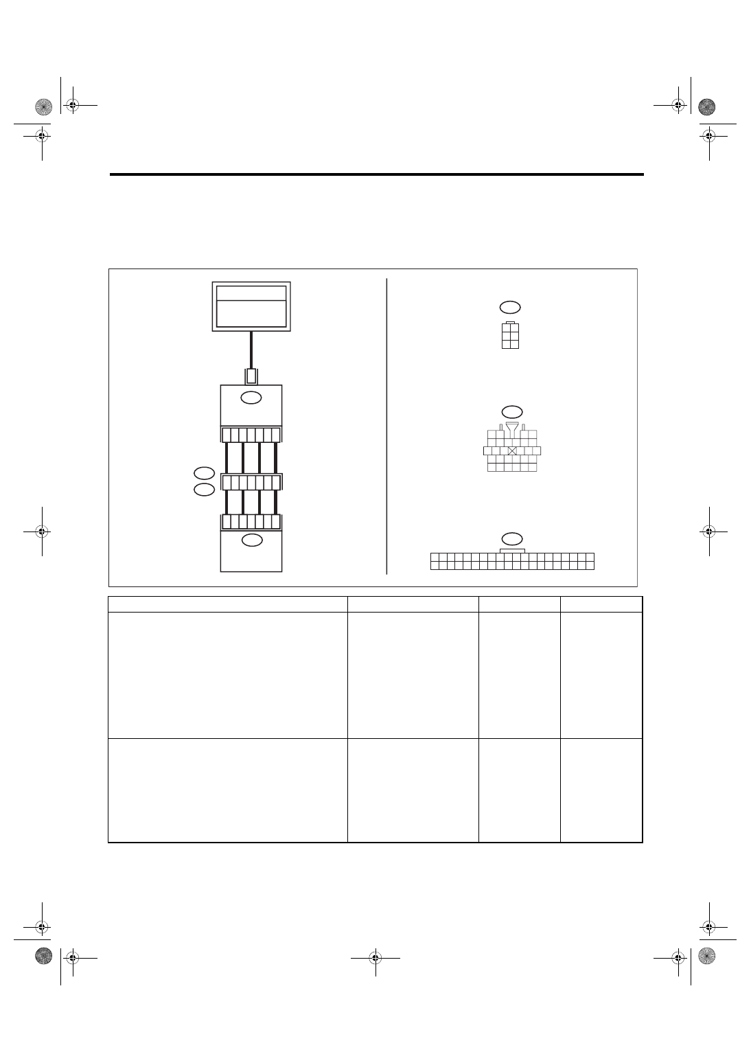
WIRING DIAGRAM:
Air conditioning system, auto A/C model <Ref. to WI-77, AUTO A/C MODEL, WIRING DIAGRAM, Air Con-
Step
Check
Yes
No
1
CHECK POWER SUPPLY OF AIR MIX DOOR
ACTUATOR.
1) Turn the ignition switch to OFF.
2) Disconnect the air mix door actuator con-
nector.
3) Turn the ignition switch to ON.
4) Measure the voltage between the air mix
door actuator connector terminal and chassis
ground.
Connector & terminal
(B239) No. 3 (+) — Chassis ground (–):
Is the voltage approx. 10 V or
more?
Check the DC
power supply cir-
cuit.
2
CHECK AIR MIX DOOR ACTUATOR.
1) Turn the ignition switch to OFF.
2) Measure the resistance between air mix
door actuator terminals using a tester.
Connector & terminal
(B239) No. 3 — No. 1:
(B239) No. 3 — No. 2:
(B239) No. 3 — No. 5:
(B239) No. 3 — No. 6:
Is the resistance 80 — 100 Ω? Go to step
Replace the air mix
door actuator.
i1
5 6 7 8
2
1
9
4
3
10
24
22
23
25
27
26
28
11 12 13
14 15 16
17 18 19 20 21
19
27
1
8
2
8
2
5
1
6
B239
2
8
27
26
25
i88
i1
B36
1 2
3 4
5 6
B239
i88
1 2 3 4 5 6 7 8 9 10 11 12 13 14 15 16 17 18 19 20
21 22 23 24 25 26 27 28 29 30 31 32 33 34 35 36 37 38 39 40
3
AC-02430
TO POWER
SUPPLY CIRCUIT
FB-18
F/B FUSE NO. 7
(B)
AUTO A/C
CONTROL
MODULE
AIR MIX DOOR
ACTUATOR
AC(diag)-28
Diagnostic Procedure for Actuators
HVAC SYSTEM (AUTO A/C) (DIAGNOSTICS)
3
CHECK HARNESS BETWEEN AUTO A/C
CONTROL MODULE AND AIR MIX DOOR
ACTUATOR.
1) Disconnect the auto A/C control module
connector.
2) Measure the resistance between auto A/C
control module and air mix door actuator con-
nector.
Connector & terminal
(B239) No. 1 — (i88) No. 28:
(B239) No. 2 — (i88) No. 27:
(B239) No. 5 — (i88) No. 26:
(B239) No. 6 — (i88) No. 25:
Is the resistance less than 1 Ω? Go to step
Repair the harness
between auto A/C
control module and
air mix door actua-
tor.
4
CHECK FOR POOR CONTACT.
Check poor contact of auto A/C control module
and connector.
Is there poor contact of connec-
tor?
Repair the connec-
tor.
Replace the auto
A/C control mod-
ule. <Ref. to AC-
31, REMOVAL,
Control Unit (Auto
A/C Model).>
Step
Check
Yes
No
Нет комментариевНе стесняйтесь поделиться с нами вашим ценным мнением.
Текст