Subaru Legacy (2005 year). Service manual — part 785
VDC(diag)-5
VEHICLE DYNAMICS CONTROL (VDC) (DIAGNOSTICS)
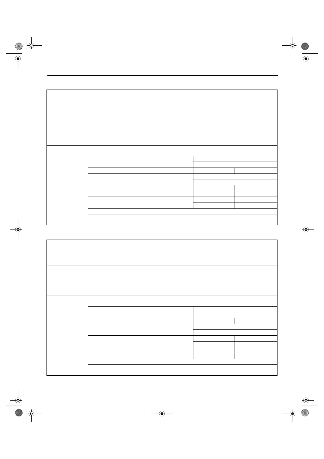
Check List for Interview
2. STATE OF VDC WARNING LIGHT AND VDC OFF INDICATOR LIGHT
3. STATE OF VDC OPERATION INDICATOR LIGHT
VDC warning light
and VDC OFF indi-
cator light come on.
❏ Always
❏ Sometimes
❏ Only once
❏ Not come on
• When / How long does it come on?
Ignition key position
❏ LOCK
❏ ACC
❏ ON (before starting engine)
❏ START
❏ ON (after engine starting, engine is running)
❏ ON (after engine starting, engine is at a standstill)
Timing
❏ Immediately after turning the ignition switch to ON
❏ Immediately after turning the ignition switch to START
❏ When accelerating
—
km/h
—
MPH
❏ When driving at a constant speed
km/h
MPH
❏ When decelerating
—
km/h
—
MPH
❏ When turning to the right
Steering angle:
deg
Steering time:
Sec.
❏ When turning to the left
Steering angle:
deg
Steering time:
Sec.
❏ When operating other electrical parts
• Part name:
• Operating condition:
VDC operation indi-
cator light comes on.
❏ Always
❏ Sometimes
❏ Only once
❏ Not come on
• When / How long does it come on?
Ignition key position
❏ LOCK
❏ ACC
❏ ON (before starting engine)
❏ START
❏ ON (after engine starting, engine is running)
❏ ON (after engine starting, engine is at a standstill)
Timing
❏ Immediately after turning the ignition switch to ON
❏ Immediately after turning the ignition switch to START
❏ When accelerating
—
km/h
—
MPH
❏ When driving at a constant speed
km/h
MPH
❏ When decelerating
—
km/h
—
MPH
❏ When turning to the right
Steering angle:
deg
Steering time:
Sec.
❏ When turning to the left
Steering angle:
deg
Steering time:
Sec.
❏ When operating other electrical parts
• Part name:
• Operating condition:

VDC(diag)-6
VEHICLE DYNAMICS CONTROL (VDC) (DIAGNOSTICS)
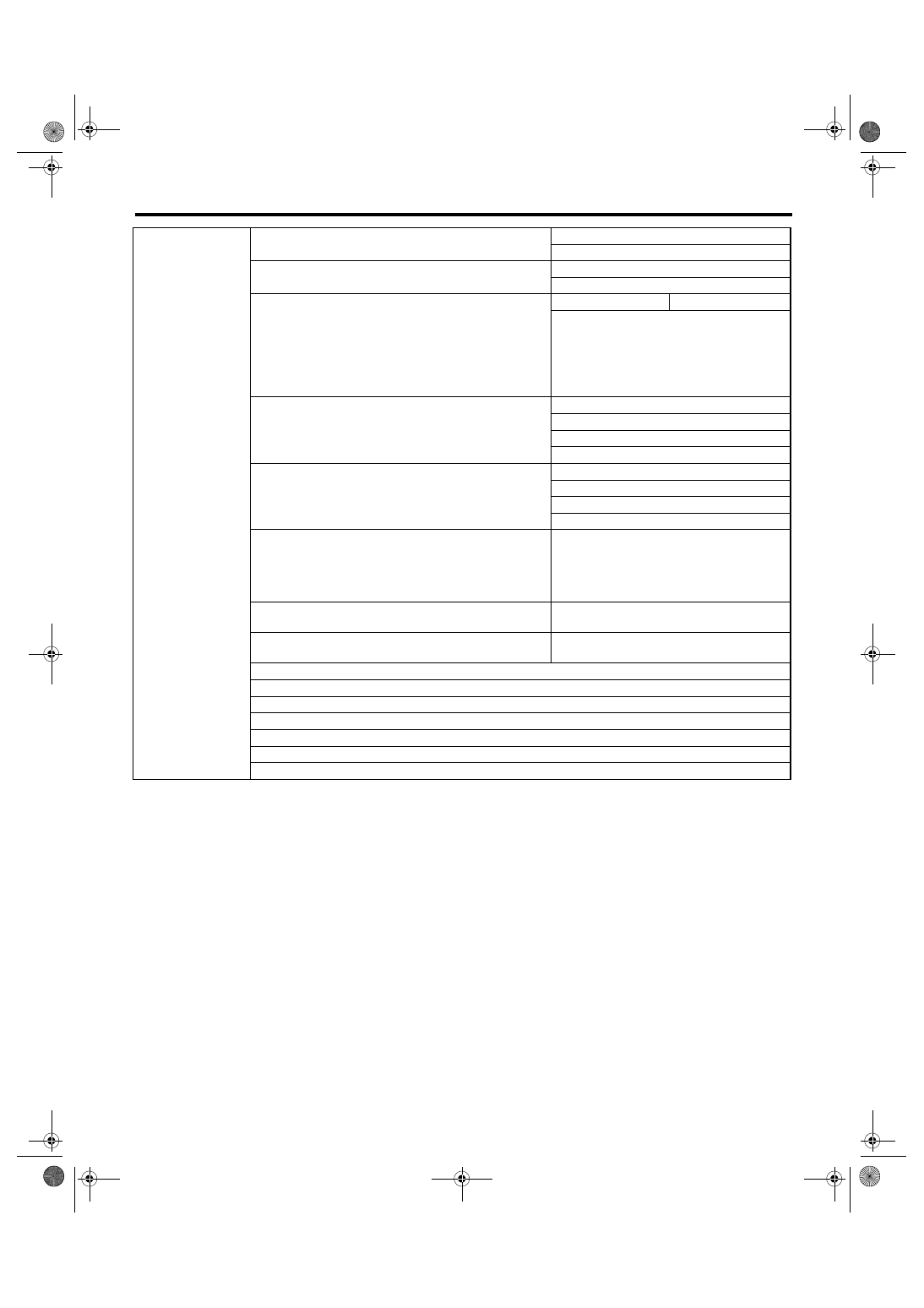
Check List for Interview
4. CONDITIONS UNDER WHICH TROUBLE OCCURS
Environment
a) Weather
❏ Fine
❏ Cloudy
❏ Rainy
❏ Snowy
❏ Others:
b) Ambient temperature
°C (°F)
c) Road
❏ Inner city
❏ Suburbs
❏ Highway
❏ Local street
❏ Uphill
❏ Downhill
❏ Paved road
❏ Gravel road
❏ Muddy road
❏ Sandy place
❏ Straight road
❏ Sharp curve
❏ Gentle curve
❏ S-curve
❏ Road with a slope on both sides
❏ Others:
d) Road surface
❏ Dried
❏ Wet
❏ Covered with fresh snow
❏ Covered with hardened snow
❏ Frozen slope
❏ Others:
VDC(diag)-7
VEHICLE DYNAMICS CONTROL (VDC) (DIAGNOSTICS)
Check List for Interview
Condition
a) Brakes
Deceleration:
G
❏ continuous / ❏ intermittent
b) Accelerator
Acceleration:
G
❏ continuous / ❏ intermittent
c) Vehicle speed
km/h
MPH
❏ Advancing
❏ When accelerating
❏ When decelerating
❏ At low speed
❏ When turning
❏ Others:
d) Tire inflation pressure
Front RH tire:
kPa
Front LH tire:
kPa
Rear RH tire:
kPa
Rear LH tire:
kPa
e) Degree of wear
Front RH tire:
Front LH tire:
Rear RH tire:
Rear LH tire:
f) Steering wheel
❏ Sharp turning
❏ Gentle turning
❏ Straight forward motion
❏ Gentle return
❏ Sharp return
g) Tire/Wheel size
❏ Specified size
❏ Except specification (
)
h) Tire variation
❏ Summer tire
❏Studless tire (Brand:
)
i) Tire chains are fitted:
❏ Yes / ❏ No
j) T-type tire is used:
❏ Yes / ❏ No
k) Condition of suspension alignment:
l) Loading state:
m) Repair parts are used:
❏ Yes / ❏ No
• Contents:
n) Others:
VDC(diag)-8
VEHICLE DYNAMICS CONTROL (VDC) (DIAGNOSTICS)
General Description
3. General Description
A: CAUTION
1. SUPPLEMENTAL RESTRAINT SYSTEM
“AIRBAG”
Airbag system wiring harness is routed near the
ABS wheel speed sensor and VDCCM&H/U.
CAUTION:
• All airbag system wiring harness and con-
nectors are colored yellow. Do not use the elec-
trical test equipment on these circuits.
• Be careful not to damage the airbag system
wiring harness when servicing the ABS wheel
speed sensor and VDCCM&H/U.
B: INSPECTION
Before performing diagnosis, check the following
items which might affect VDC problems.
1. BATTERY
Measure the battery voltage and check electrolyte.
Standard voltage: 12 V or more
Specific gravity: 1.260 or more
2. GROUND
Check the tightening torque of ground (GB-7) bolt
of VDC.
Tightening torque:
13 N
⋅
m (1.3 kgf-m, 9.6 ft-lb)
3. BRAKE FLUID
1) Check the brake fluid level.
2) Check the brake fluid for leaks.
4. HYDRAULIC UNIT
Check the hydraulic unit.
• With brake tester <Ref. to VDC-8, CHECKING
THE HYDRAULIC UNIT ABS OPERATION WITH
BRAKE TESTER, INSPECTION, VDC Control
Module and Hydraulic Control Unit (VDCCM&H/
U).>
• Without brake tester <Ref. to VDC-8, CHECK-
ING THE HYDRAULIC UNIT ABS OPERATION
BY PRESSURE GAUGE, INSPECTION, VDC
Control Module and Hydraulic Control Unit (VDC-
CM&H/U).>
5. BRAKE DRAG
Check for brake drag.
6. BRAKE PAD AND ROTOR
Check the brake pad and rotor.
• FRONT <Ref. to BR-18, INSPECTION, Front
Brake Pad.> <Ref. to BR-19, INSPECTION, Front
Disc Rotor.>
• REAR <Ref. to BR-25, INSPECTION, Rear
Brake Pad.> <Ref. to BR-26, INSPECTION, Rear
Disc Rotor.>
7. TIRE
Check the tire specifications, tire wear and air pres-
sure. <Ref. to WT-2, SPECIFICATION, General
Description.>
Нет комментариевНе стесняйтесь поделиться с нами вашим ценным мнением.
Текст