Subaru Legacy (2005 year). Service manual — part 937
WW-5
WIPER AND WASHER SYSTEMS
General Description
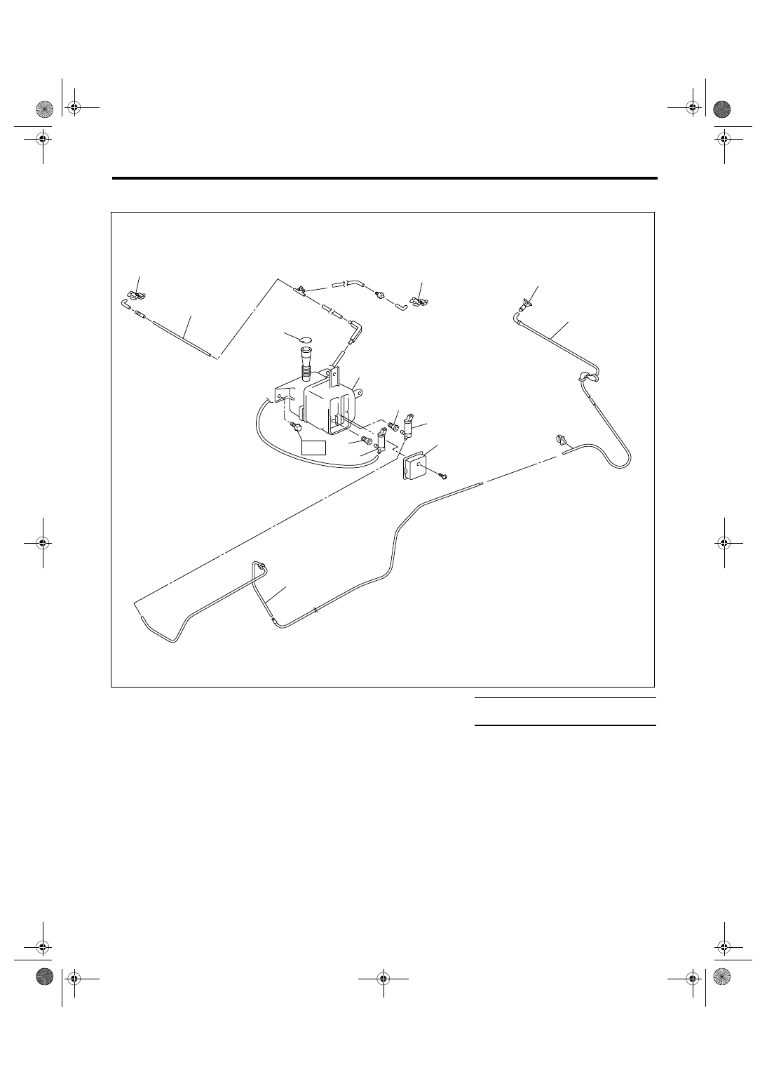
3. WASHER TANK
(1)
Washer nozzle
(6)
Rear washer motor (Wagon
model)
Tightening torque: N
⋅
m (kgf-m, ft-lb)
(2)
Washer hose
T: 6.0 (0.61, 4.3)
(3)
Washer tank
(7)
Grommet
(4)
Washer tank cap
(8)
Washer motor cover
(5)
Front washer motor
WW-00329
(2)
(7)
(6)
(5)
(2)
(4)
(3)
(7)
T
(1)
(8)
(1)
(2)
(1)
WW-6
WIPER AND WASHER SYSTEMS
General Description
C: CAUTION
• Connect the connectors and hoses securely dur-
ing reassembly.
• After reassembly, make sure functional parts op-
erate smoothly.
• Be careful that wire harnesses of airbag system
pass near electrical parts and switches.
• Wiring harnesses and connectors of all airbag
system are yellow color. Do not use a tester equip-
ment on these circuits.
• Care must be taken when connecting the piping
hose so that no bending, jamming, etc. are caused.
• If even a little oil or grease such as silicon oil gets
in the tank and washer passages, an oil film is eas-
ily formed on the glass, causing the wiper to chatter
and judder, therefore, be careful not to let this hap-
pen.
WW-7
WIPER AND WASHER SYSTEMS
Wiper and Washer System
2. Wiper and Washer System
A: WIRING DIAGRAM
1. WIPER AND WASHER (FRONT) LHD MODEL
<Ref. to WI-275, LHD MODEL, WIRING DIAGRAM, Front Wiper and Washer System.>
2. WIPER AND WASHER (FRONT) RHD MODEL
<Ref. to WI-276, RHD MODEL, WIRING DIAGRAM, Front Wiper and Washer System.>
3. WIPER AND WASHER (REAR) LHD MODEL
<Ref. to WI-277, LHD MODEL, WIRING DIAGRAM, Rear Wiper and Washer System.>
4. WIPER AND WASHER (REAR) RHD MODEL
<Ref. to WI-278, RHD MODEL, WIRING DIAGRAM, Rear Wiper and Washer System.>
B: INSPECTION
Symptom
Repair order
Wiper and washers do not operate.
(1) Wiper fuse (Front: F/B No. 30, Rear: F/B No. 23)
(2) Combination switch
(3) Wiper motor assembly
(4) Wiring harness
(5) Body integrated module (rear wiper only)
Wipers do not operate in LO or HI.
(1) Combination switch
(2) Wiper motor assembly
(3) Wiring harness
Wipers do not operate in INT.
(1) Combination switch
(2) Wiper motor assembly
(3) Wiring harness
(4) Body integrated module (rear wiper only)
Washer motor does not operate.
(1) Washer switch
(2) Washer motor
(3) Wiring harness
Wipers do not operate when washer switch is ON.
(1) Wiper motor assembly
(2) Wiring harness
Washer fluid spray does not operate properly.
(1) Washer motor
(2) Washer hose and nozzle
WW-8
WIPER AND WASHER SYSTEMS
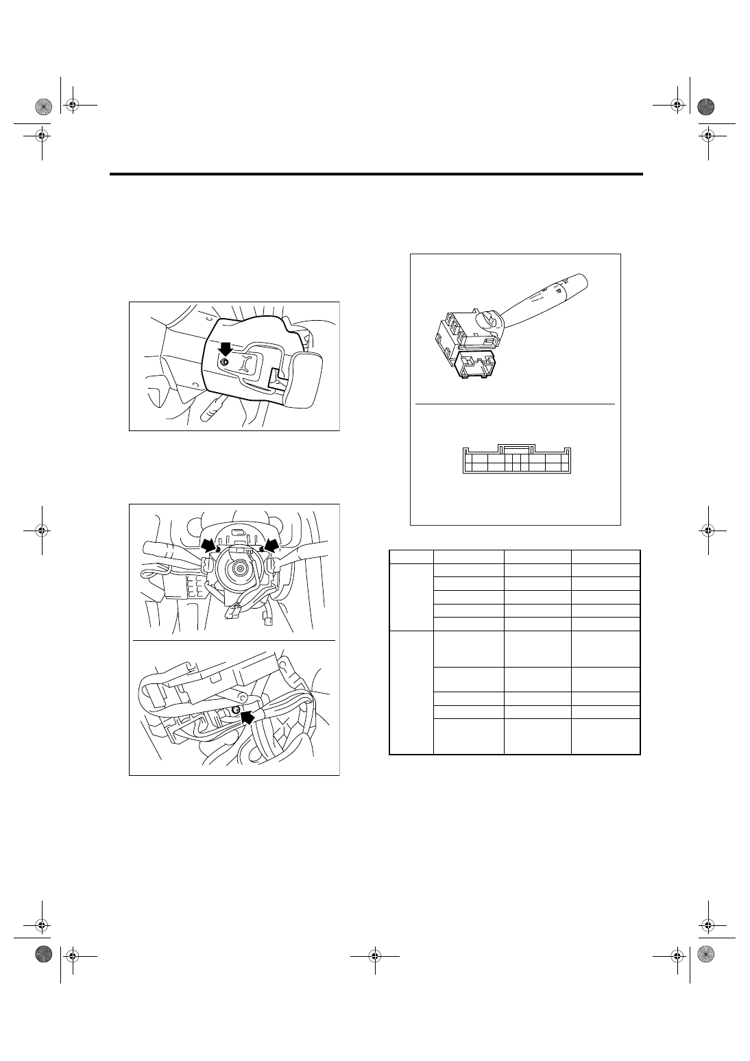
Combination Switch (Wiper)
3. Combination Switch (Wiper)
A: REMOVAL
1) Disconnect the ground cable from battery.
2) Remove the instrument panel lower cover. <Ref.
to EI-50, REMOVAL, Instrument Panel Lower Cov-
er.>
3) Remove the screw to remove steering column
cover (upper and lower).
4) Disconnect the connector from combination
switch.
5) Remove the three screws, and pull out the com-
bination base switch assembly toward you. (EC,
EK, KS and K4 model)
6) Remove the screws which secure switch, then
remove the combination switch.
B: INSTALLATION
Install in the reverse order of removal.
C: INSPECTION
1. COMBINATION SWITCH
1) Inspect the continuity between each connector
terminal.
• EC, EK, KS, EH, ER and K4 model
SL-00258
LI -00332
Switch position
Terminal No.
Standard
Front
OFF
7 and 16
Less than 1
Ω
INT
7 and 16
Less than 1
Ω
LO
7 and 17
Less than 1
Ω
HI
8 and 17
Less than 1
Ω
Washer ON
2 and 11
Less than 1
Ω
Rear
(Wagon
model)
Washer ON
2 and 11
12 and 10
2 and 10
Less than 1
Ω
OFF
—
More than 1
M
Ω
INT
2 and 13
Less than 1
Ω
ON
2 and 10
Less than 1
Ω
Washer ON
2 and 12
12 and 10
2 and 10
Less than 1
Ω
WW-00046
8
7
6 5 4
3
2
1
9
17
16 15 14 13 12
11 10
18
Нет комментариевНе стесняйтесь поделиться с нами вашим ценным мнением.
Текст