Subaru Legacy (2005 year). Service manual — part 938
WW-9
WIPER AND WASHER SYSTEMS
Combination Switch (Wiper)
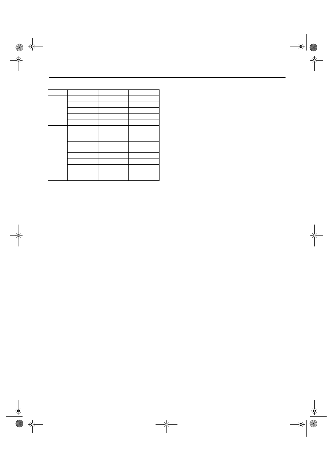
• KA model
2) If continuity is not as specified, replace the
switch.
Switch position
Terminal No.
Standard
Front
OFF
3 and 12
Less than 1
Ω
INT
3 and 12
Less than 1
Ω
LO
3 and 11
Less than 1
Ω
HI
2 and 11
Less than 1
Ω
Washer ON
8 and 17
Less than 1
Ω
Rear
(Wagon
model)
Washer ON
8 and 16
16 and 18
8 and 18
Less than 1
Ω
OFF
—
More than 1
M
Ω
INT
8 and 15
Less than 1
Ω
ON
8 and 18
Less than 1
Ω
Washer ON
8 and 16
16 and 18
8 and 18
Less than 1
Ω
WW-10
WIPER AND WASHER SYSTEMS
Combination Switch (Wiper)
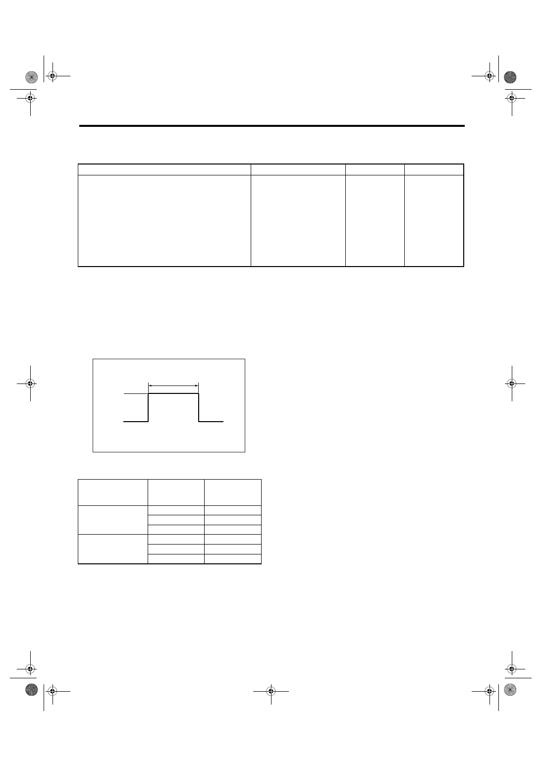
2. FRONT WIPER
1) Check with Subaru Select Monitor.
2) Intermittent operation inspection
(1) Turn the wiper switch to INT.
(2) Adjust the intermittent control switch to MAX.
(3) Apply the battery voltage to switch terminal No. 16 and 2 (EC, EK, KS and K4 model) or terminal No.
12 and 8 (KA model).
(4) Measure the voltage between combination switch terminals and measure the intermittent downtime.
Terminal
No. 3 — No. 8:
3) If operation is not as specified, replace the switch.
Step
Check
Yes
No
1
CHECK INPUT SIGNAL TO BODY INTE-
GRATED MODULE.
When the front wiper switch is operated, check
the input signal using Subaru Select Monitor.
1) Connect the Subaru Select Monitor to data
link connector.
2) Turn the ignition switch to ON.
3) Select {Integ.unit} from main menu.
4) Select the {Current Data Display & Save}.
5) When the front wiper switch is set to LO or
HI, check the input signal.
Is the input signal normal?
End.
Replace the body
integrated mod-
ule. <Ref. to SL-
44, Body Inte-
grated Module.>
S: Intermittent downtime (sec.)
Switch position
Vehicle speed
(km/h (MPH))
Intermittent
downtime
(sec.)
MIN.
0 (0)
Approx. 4
30 (19)
Approx. 1.5
60 (37)
Approx. 1
MAX.
0 (0)
Approx. 20
30 (19)
Approx. 18.5
60 (37)
Approx. 16
S
12 V
0 V
WW-00323
WW-11
WIPER AND WASHER SYSTEMS
Combination Switch (Wiper)
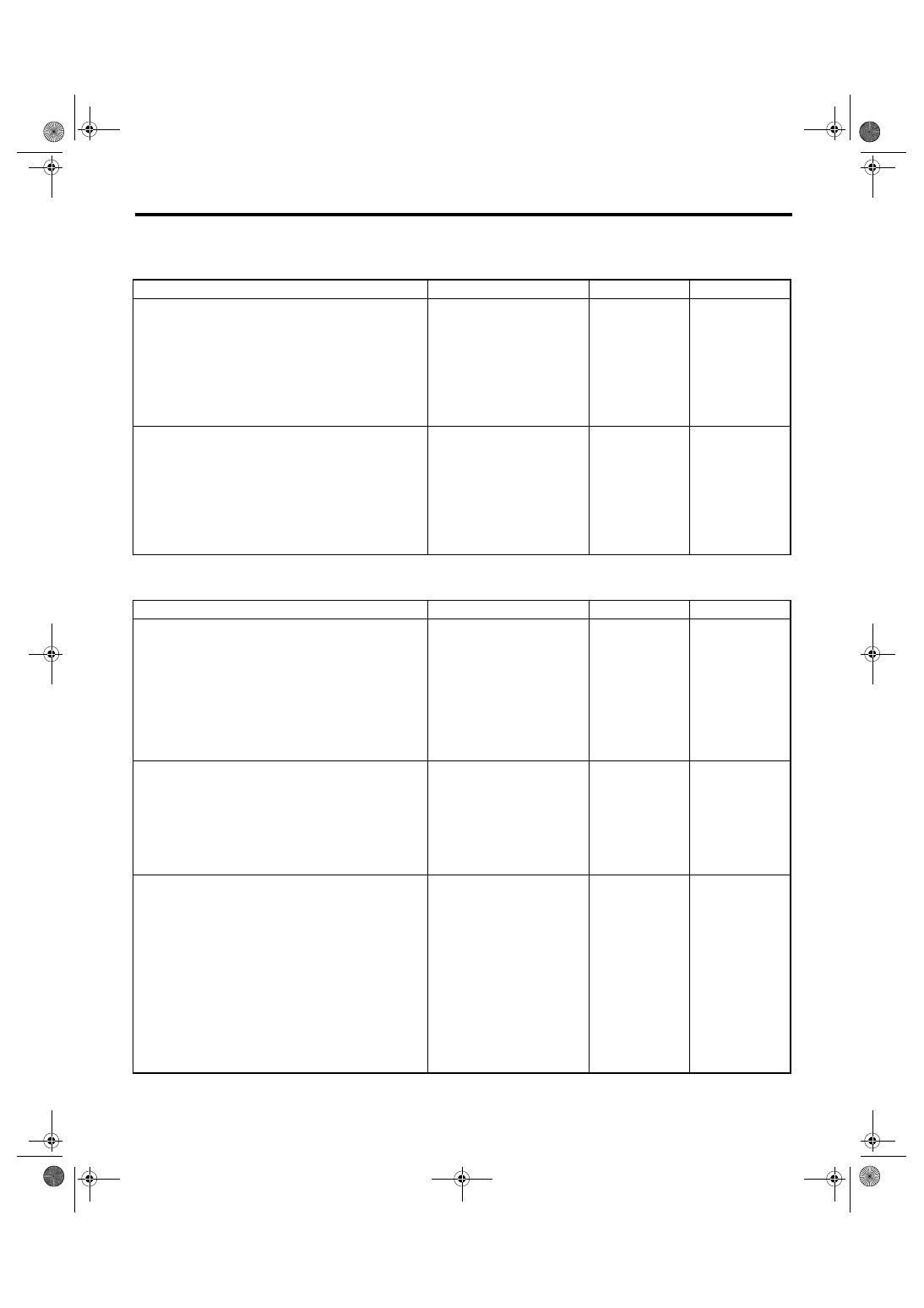
3. REAR WIPER
1) Check with Subaru Select Monitor.
2) Rear wiper motor circuit check
Step
Check
Yes
No
1
CHECK INPUT OF REAR WIPER SWITCH.
Check the input from body integrated module
using Subaru Select Monitor.
1) Connect the Subaru Select Monitor to data
link connector.
2) Turn the ignition switch to ON.
3) Select {Integ.unit} from main menu.
4) Select the {Current Data Display & Save}.
5) Check the input of rear wiper switch.
Is the input normal?
Check the rear
wiper switch. <Ref.
to WW-8,
INSPECTION,
Combination
Switch (Wiper).>
2
CHECK OUTPUT OF BODY INTEGRATED
MODULE.
When the rear wiper switch is operated, check
the output using Subaru Select Monitor.
1) Turn the ignition switch to ON.
2) Operate the rear wiper switch to set to each
position of ON and INT.
3) At this time, check the output of body inte-
grated module.
When it is set to ON, is ON out-
put continuously? When it is
set to INT, is ON/OFF output
repeatedly? (INT OFF time
(when vehicle parked): 12 sec-
onds for Wagon)
Check the rear
wiper motor. <Ref.
to WW-22,
INSPECTION,
Rear Wiper
Motor.>
Replace the body
integrated mod-
ule. <Ref. to SL-
44, Body Inte-
grated Module.>
Step
Check
Yes
No
1
CHECK POWER SUPPLY CIRCUIT OF REAR
WIPER MOTOR.
1) Disconnect the harness connector of rear
wiper motor.
2) Turn the ignition switch to ACC.
3) Measure the voltage between the rear
wiper motor harness connector terminal and
chassis ground.
Connector & terminal
(D43) No. 1 (+) — Chassis ground (
−
):
Is the voltage more than 10 V? Go to step 2.
• Check the fuse
(No. 23 in fuse &
relay box).
• Check the fus-
ible link (No. 7 in
main fuse box).
2
CHECK GROUND CIRCUIT OF REAR WIPER
MOTOR.
1) Turn the ignition switch to OFF.
2) Measure the resistance between the rear
wiper motor harness connector terminal and
chassis ground.
Connector & terminal
(D43) No. 3 — Chassis ground:
Is the resistance less than 10
Ω?
Repair the open
circuit of rear wiper
motor ground cir-
cuit.
3
CHECK HARNESS BETWEEN BODY INTE-
GRATED MODULE AND REAR WIPER MO-
TOR.
1) Turn the ignition switch to OFF.
2) Disconnect the body integrated module
harness connector.
3) Disconnect the harness connector of rear
wiper motor.
4) Measure the resistance between the har-
ness connector terminals of body integrated
module and rear wiper motor.
Connector & terminal
(B280) No. 1 — (D43) No. 2:
(B280) No. 8 — (D43) No. 4:
Is the resistance less than 10
Ω?
Repair the open
circuit of harness
between body inte-
grated module and
rear wiper motor.
WW-12
WIPER AND WASHER SYSTEMS
Combination Switch (Wiper)
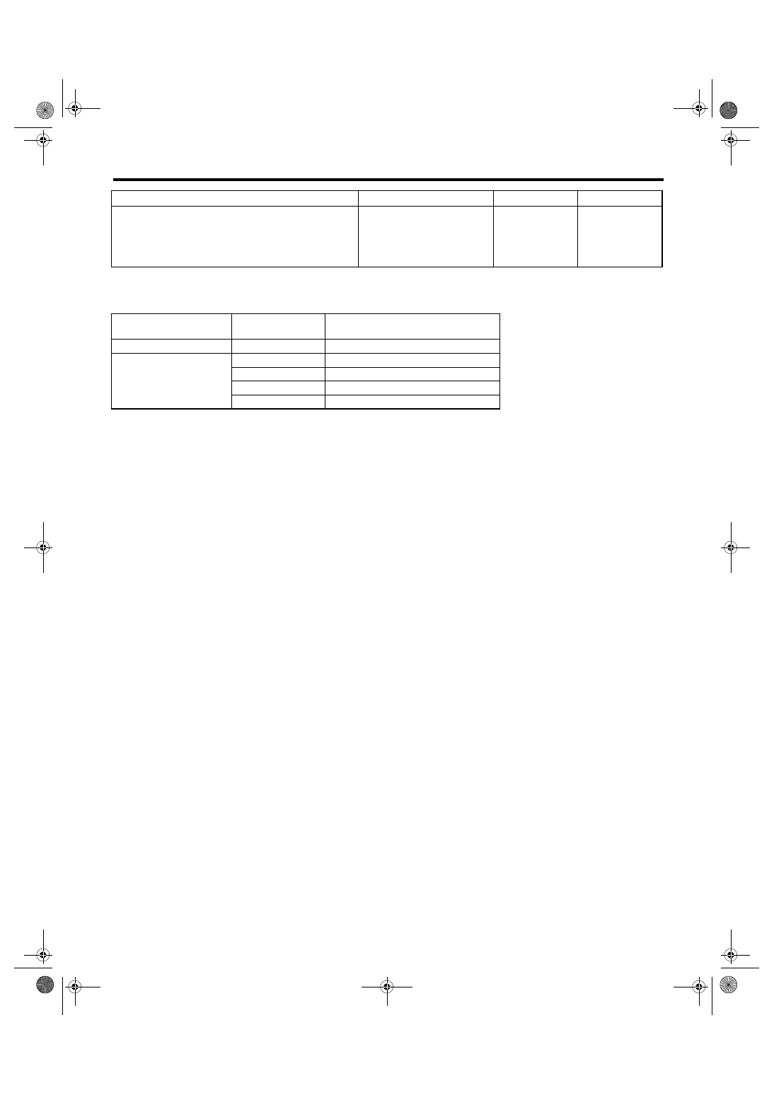
NOTE:
Rear wiper intermittent time (AT model)
4
CHECK OPERATION OF REAR WIPER MO-
TOR.
1) Remove the rear wiper motor.
2) Check the rear wiper motor. <Ref. to WW-
22, INSPECTION, Rear Wiper Motor.>
Does the rear wiper motor
rotate normally?
End.
Replace the rear
wiper motor.
Select lever position
(AT model)
Vehicle speed
(km/h (MPH))
Intermittent stopping time (sec.)
Rev
—
Continuous operation
Except for reverse mode
80 — (50 —)
3
50 — 80 (31 — 50)
6
20 — 50 (12 — 31)
9
0 — 20 (0 — 12)
12
Step
Check
Yes
No
Нет комментариевНе стесняйтесь поделиться с нами вашим ценным мнением.
Текст