Subaru Legacy (2005 year). Service manual — part 935
LI-37
LIGHTING SYSTEM
Trunk Room Light
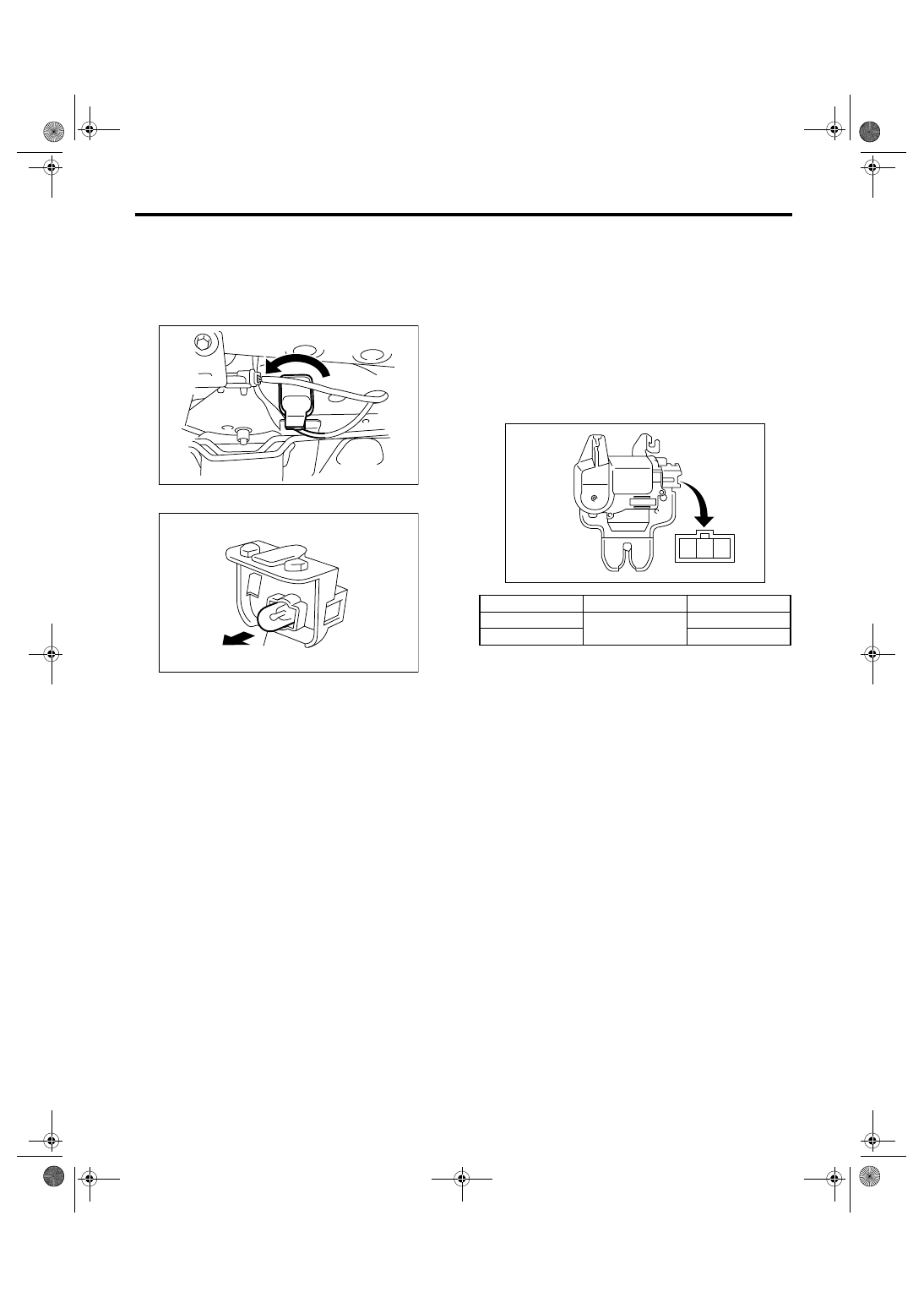
32.Trunk Room Light
A: REMOVAL
1) Disconnect the ground cable from battery.
2) Turn the trunk room light to the left for 60
° to re-
move it and disconnect the harness connector.
3) Remove the bulb (A).
B: INSTALLATION
Install in the reverse order of removal.
C: INSPECTION
1. TRUNK ROOM LIGHT BULB
1) Visually check the bulb for blow out.
2) Check the bulb specification. <Ref. to LI-2,
SPECIFICATION, General Description.>
3) If NG, replace the bulb with a new one.
2. TRUNK LID SWITCH (TRUNK ROOM
LIGHT SWITCH)
Measure the resistance between trunk lid switch
terminals.
LI-00321
LI-00286
(A)
Trunk lid position
Terminal No.
Standard
Close
1 and 3
More than 1 M
Ω
Open
1.5
±0.5 Ω
LI-00290
3
2
1
LI-38
LIGHTING SYSTEM
Glove Box Light
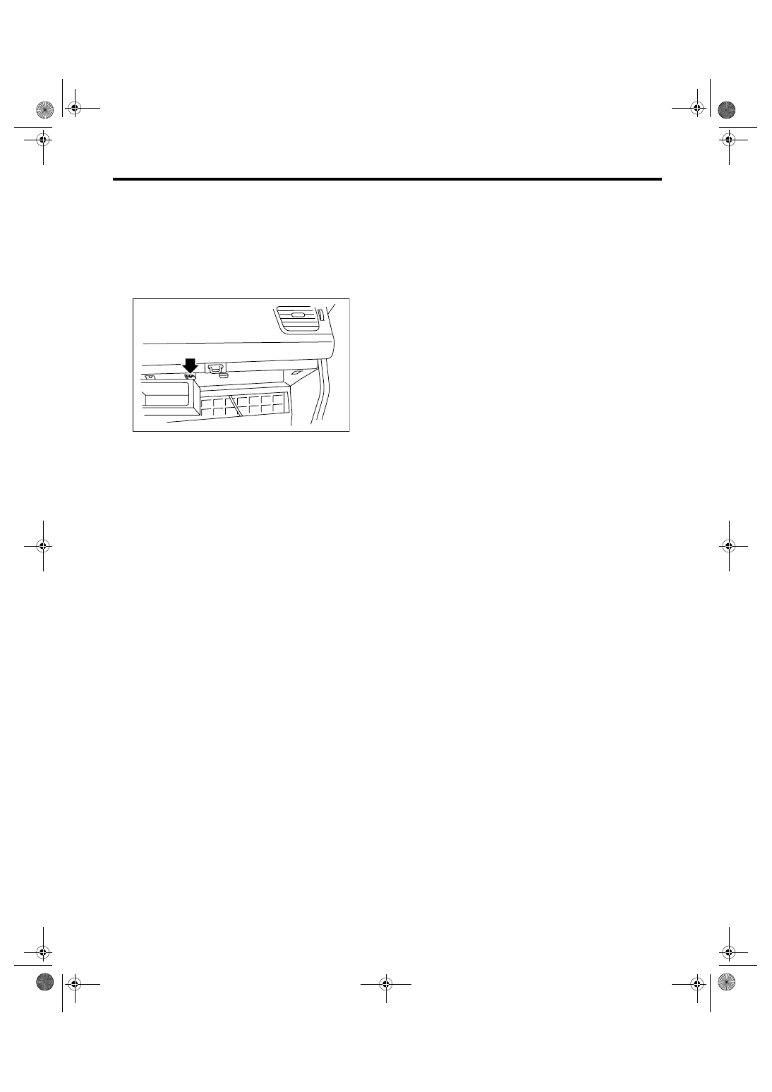
33.Glove Box Light
A: REMOVAL
1) Disconnect the ground cable from battery.
2) Remove the glove box. <Ref. to EI-51, REMOV-
AL, Glove Box.>
3) Disconnect the harness connector.
4) Remove the glove box light.
B: INSTALLATION
Install in the reverse order of removal.
C: INSPECTION
1) Visually check the bulb for blow out.
2) Check the bulb specification.
<Ref. to LI-2, SPECIFICATION, General Descrip-
tion.>
3) If NG, replace the bulb with a new one.
LI-00323
LI-39
LIGHTING SYSTEM
Door Step Light
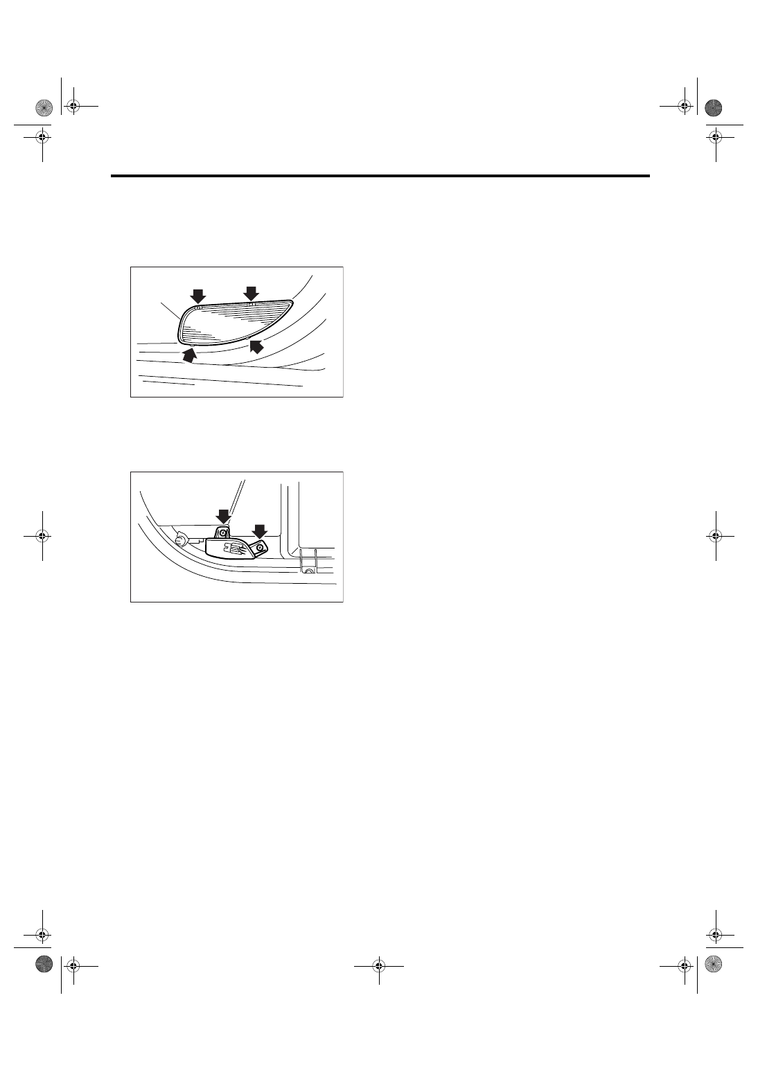
34.Door Step Light
A: REMOVAL
1) Disconnect the ground cable from battery.
2) Remove the lens (A), and then remove the door
step light bulb.
3) Remove the front door trim. <Ref. to EI-48, RE-
MOVAL, Door Trim.>
4) Disconnect the harness connector.
5) Remove the mounting screw from rear side of
trim and remove the door step light.
B: INSTALLATION
Install in the reverse order of removal.
C: INSPECTION
1) Visually check the bulb for blow out.
2) Check the bulb specification.
<Ref. to LI-2, SPECIFICATION, General Descrip-
tion.>
3) If NG, replace the bulb with a new one.
LI-00266
(A)
LI-00267
LI-40
LIGHTING SYSTEM
Ignition Switch Illumination
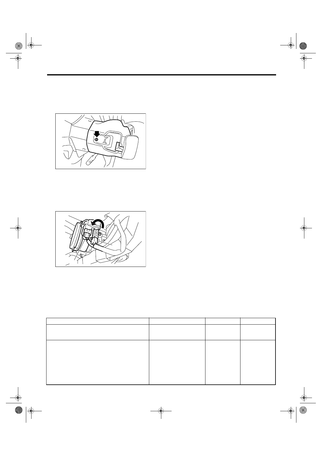
35.Ignition Switch Illumination
A: REMOVAL
1) Disconnect the ground cable from battery.
2) Remove the screws and detach the upper col-
umn cover and lower column cover.
3) Remove the instrument panel lower cover. <Ref.
to EI-50, REMOVAL, Instrument Panel Lower Cov-
er.>
4) Disconnect the ignition switch illumination con-
nector (A).
5) Turn the ignition switch illumination connector to
left and remove it.
B: INSTALLATION
Install in the reverse order of removal.
C: INSPECTION
(A) Ignition switch illumination connector
(B) Ignition switch illumination
(C) Immobilizer antenna connector
SL-00258
LI-00343
(C)
(B)
(A)
Step
Check
Yes
No
1
CHECK IGNITION SWITCH ILLUMINATION.
Make sure the ignition switch illumination illu-
minates when driver’s side door is open.
Does the ignition switch illumi-
nation illuminate?
Ignition switch illu-
mination is normal.
2
CHECK IGNITION SWITCH ILLUMINATION.
Make sure the ignition switch illumination
blinks when ignition switch is turned to ON.
Does the ignition switch illumi-
nation blink?
Check the func-
tion setting of body
integrated mod-
ule. <Ref. to
LAN(diag)-2, Basic
Diagnostic Proce-
dure.>
Check the ignition
switch illumination
circuit. <Ref. to
SL-25, CHECK
IGNITION
SWITCH ILLUMI-
NATION, INSPEC-
TION, Keyless
Entry System.>
Нет комментариевНе стесняйтесь поделиться с нами вашим ценным мнением.
Текст