Subaru Legacy (2005 year). Service manual — part 793
VDC(diag)-37
VEHICLE DYNAMICS CONTROL (VDC) (DIAGNOSTICS)
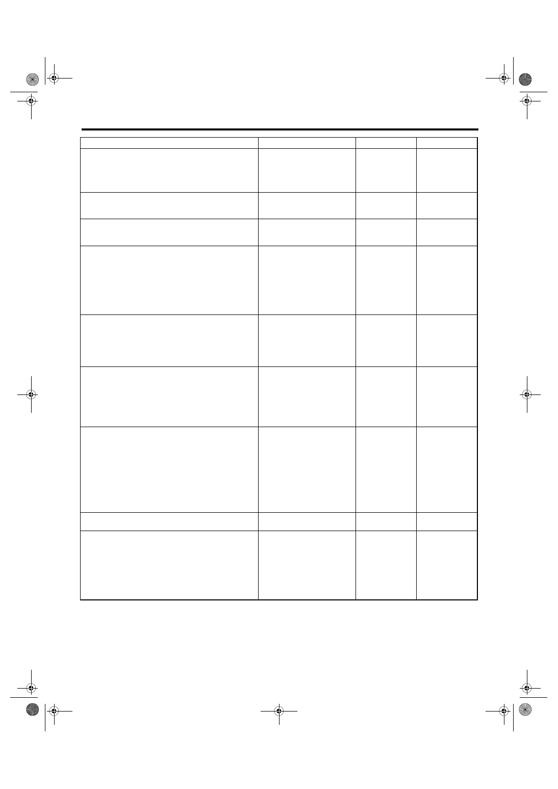
Warning Light Illumination Pattern
Step
Check
Yes
No
1
CHECK INSTALLATION OF VDCCM&H/U
CONNECTOR.
1) Turn the ignition switch to OFF.
2) Check that VDCCM&H/U connector is
inserted until it is locked by clamp.
Is the connector firmly
inserted?
Insert VDCCM&H/
U connector until it
is locked by clamp.
2
READ DTC.
Read the DTC. <Ref. to VDC(diag)-23, Read
Diagnostic Trouble Code (DTC).>
Is DTC displayed?
Perform the diag-
nosis according to
DTC.
3
CHECK BRAKE FLUID AMOUNT.
Check the amount of brake fluid in the reser-
voir tank of master cylinder.
Is the amount of brake fluid
between the lines of “MAX”
and “MIN”?
Replenish brake
fluid to the speci-
fied value.
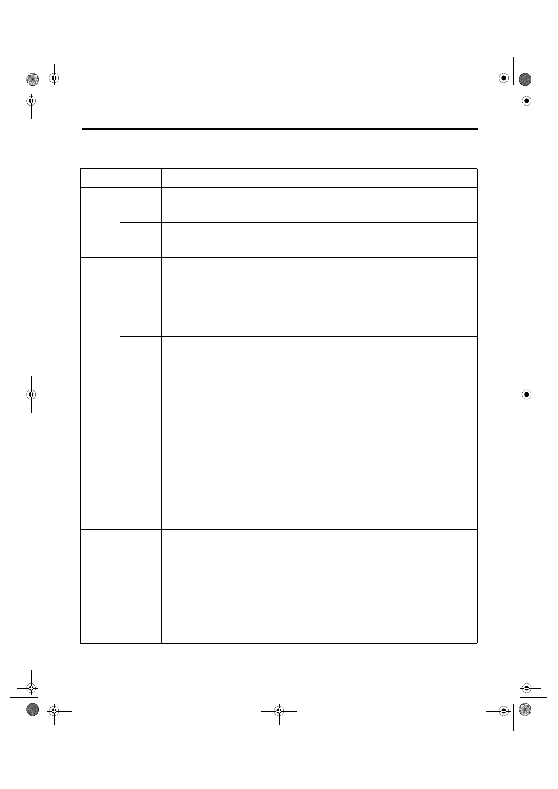
4
CHECK BRAKE FLUID LEVEL SWITCH.
1) Turn the ignition switch to OFF.
2) Disconnect the level switch connector (B16)
from master cylinder.
3) Measure the resistance of master cylinder
terminals.
Terminals
No. 1 — No. 2:
Is the resistance more than 1
M
Ω?
Replace the mas-
ter cylinder.
5
CHECK PARKING BRAKE SWITCH.
1) Disconnect the connector (R4) from park-
ing brake switch.
2) Release the parking brake.
3) Measure the resistance between parking
brake switch terminal and chassis ground.
Is the resistance more than 1
M
Ω?
Replace the park-
ing brake switch.
6
CHECK GROUND SHORT OF HARNESS.
1) Disconnect the connector (i10) from combi-
nation meter.
2) Measure the resistance between combina-
tion meter connector and chassis ground.
Connector & terminal
(i10) No. 7 — Chassis ground:
Is the resistance more than 1
M
Ω?
Repair the har-
ness connector
between combina-
tion meter brake
fluid level switch
and parking brake
switch.
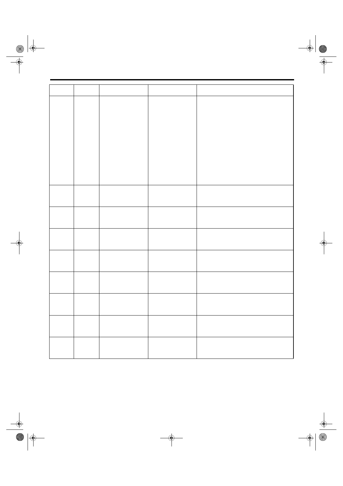
7
CHECK HARNESS CONNECTOR.
1) Disconnect the connector (B310) from
VDCCM&H/U.
2) Disconnect the connector (i10) from combi-
nation meter.
3) Measure the resistance between
VDCCM&H/U connector and combination
meter connector.
Connector & terminal
(B310) No. 20 — (i10) No. 7:
Is the resistance less than 0.5
Ω?
Repair the har-
ness connector
between
VDCCM&H/U and
combination
meter.
8
CHECK POOR CONTACT IN CONNECTOR.
Check poor contact in all connectors.
Is there poor contact?
Repair the con-
nector.
9
CHECK VDCCM.
1) Connect the connector (B310) to
VDCCM&H/U.
2) Turn the ignition to ON.
3) Measure the resistance between combina-
tion meter connector and chassis ground.
Connector & terminal
(i10) No. 7 — Chassis ground:
Is the resistance less than 0.5
Ω?
Check the combi-
nation meter.
Replace the
VDCCM&H/U.
VDC(diag)-38
VEHICLE DYNAMICS CONTROL (VDC) (DIAGNOSTICS)
List of Diagnostic Trouble Code (DTC)
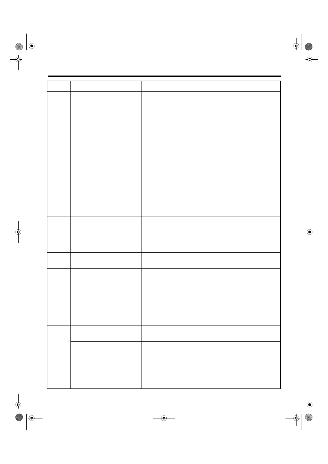
11.List of Diagnostic Trouble Code (DTC)
A: LIST
DTC
Detailed
code
Display
Contents of diagnosis
Reference target
C0021
698XH
FR sensor power supply
failure
Abnormal power sup-
ply of front ABS wheel
speed sensor RH
6A0XH
Front Right ABS Sensor
Circuit Open or Shorted
Battery
Open / high input of
front ABS wheel speed
sensor RH
C0022
68CXH
68EXH
690XH
694XH
696XH
Front Right ABS Sensor
Signal
Front ABS wheel speed
sensor RH signal mal-
function
C0023
618XH
FL sensor power sup-
ply failure
Front ABS wheel speed
sensor LH power sup-
ply malfunction
620XH
Front Left ABS Sensor
Circuit Open or Shorted
Battery
Open / high input of
front ABS wheel speed
sensor LH
C0024
60CXH
60EXH
610XH
614XH
616XH
Front Left ABS Sensor
Signal
Front ABS wheel speed
sensor LH signal mal-
function
C0025
658XH
RR sensor power sup-
ply failure
Rear ABS wheel speed
sensor RH power sup-
ply malfunction
660XH
Rear Right ABS Sensor
Circuit Open or Shorted
Battery
Open / high input of
rear ABS wheel speed
sensor RH
C0026
64CXH
64EXH
650XH
654XH
656XH
Rear Right ABS Sensor
Signal
Rear ABS wheel speed
sensor RH signal mal-
function
C0027
6D8XH
RL sensor power supply
failure
Rear ABS wheel speed
sensor LH power sup-
ply malfunction
6E0XH
Rear Left ABS Sensor
Circuit Open or Shorted
Battery
Open / high input of
rear ABS wheel speed
sensor LH
C0028
6CCXH
6CEXH
6D0XH
6D4XH
6D6XH
Rear Left ABS Sensor
Signal
Rear ABS wheel speed
sensor LH signal mal-
function
VDC(diag)-39
VEHICLE DYNAMICS CONTROL (VDC) (DIAGNOSTICS)
List of Diagnostic Trouble Code (DTC)
C0029
608XH
648XH
688XH
6C8XH
704XH
606XH
646XH
686XH
6C6XH
702XH
604XH
644XH
684XH
6C4XH
70CXH
720XH
710XH
Any One of Four ABS
Sensors Signal
ABS wheel speed sen-
sor signal malfunction
in one of four wheels
C0031
320XH
FR hold valve malfunc-
tion
Front inlet solenoid
valve RH malfunction in
VDCCM&H/U
C0032
360XH
FR pressure reducing
valve malfunction
Front outlet solenoid
valve RH malfunction in
VDCCM&H/U
C0033
220XH
FL hold valve malfunc-
tion
Front inlet solenoid
valve LH malfunction in
VDCCM&H/U
C0034
260XH
FL pressure reducing
valve malfunction
Front outlet solenoid
valve LH malfunction in
VDCCM&H/U
C0035
2A0XH
RR hold valve malfunc-
tion
Rear inlet solenoid
valve RH malfunction in
VDCCM&H/U
C0036
2E0XH
RR pressure reducing
valve malfunction
Rear outlet solenoid
valve RH malfunction in
VDCCM&H/U
C0037
3A0XH
RL hold valve malfunc-
tion
Rear inlet solenoid
valve LH malfunction in
VDCCM&H/U
C0038
3E0XH
RL pressure reducing
valve malfunction
Rear outlet solenoid
valve LH malfunction in
VDCCM&H/U
DTC
Detailed
code
Display
Contents of diagnosis
Reference target
VDC(diag)-40
VEHICLE DYNAMICS CONTROL (VDC) (DIAGNOSTICS)
List of Diagnostic Trouble Code (DTC)
C0041
000XH
002XH
004XH
006XH
010XH
012XH
014XH
016XH
018XH
01AXH
01EXH
024XH
026XH
028XH
02AXH
02CXH
02EXH
030XH
03AXH
03CXH
03DXH
03EXH
034XH
036XH
038XH
ECM
VDC control module
(VDCCM) malfunction
C0042
7CEXH
7D0XH
Power supply voltage
failure
Power voltage malfunc-
tion
7CCXH
Speed sen. power sup-
ply failure
ABS wheel speed sen-
sor power malfunction
C0044
9A0XH
TCM communication
circuit
CAN communication
malfunction of transmis-
sion control module
C0045
970XH
822XH
Incorrect VDC Control
Module specifications
Different VDC control
module specification
972XH
TCM malfunction
AT control module mal-
function
C0047
788XH
78CXH
7A0XH
7A4XH
Improper CAN commu-
nication
Improper CAN commu-
nication
C0051
048XH
Valve relay OFF failure
Valve relay OFF mal-
function
04AXH
04CXH
Valve relay
Valve relay system
06AXH
Valve relay test failure
Valve relay test mal-
function
00DXH
Valve relay ON failure
Valve relay ON mal-
function
DTC
Detailed
code
Display
Contents of diagnosis
Reference target
Нет комментариевНе стесняйтесь поделиться с нами вашим ценным мнением.
Текст