Subaru Legacy (2005 year). Service manual — part 791
VDC(diag)-29
VEHICLE DYNAMICS CONTROL (VDC) (DIAGNOSTICS)
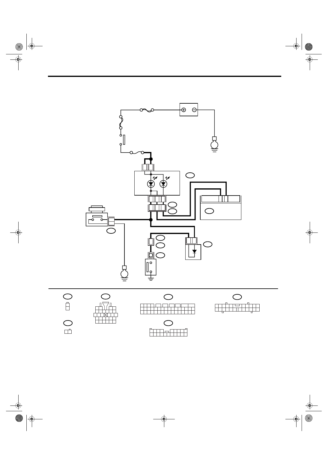
Warning Light Illumination Pattern
• RHD model
B310
i1
B16
1
2
B97
E
MAIN SBF
SBF-6
E
No.5
B16
B97
R1
R4
A3
A4
5
A8
16
1
2
1
2
B229
1 2
3 4
5 6 7 8 9 10
16
11
15
14
13
12
17
19
18
23
25
24
20
22
21
26
28
27
i10
2
1
3 4
6 7 8 9 10
22
21
20
19
18
17
16
15
14
13
12
11
5
1 2 3 4
5 6 7 8 9
10 11 12 13 14 15 16 17 18 19 20
B229
1 2
A:
BATTERY
IGNITION
SWITCH
BRAKE FLUID
LEVEL SWITCH
PARKING
BRAKE
SWITCH
BRAKE
WARNING
LIGHT
ABS
WARNING
LIGHT
20
35
B310
B36
i1
i10
A:
VDCCM & H/U
A8
A5
16
3
A7
4
1 2 3 4
11 12 13 14
27 28 29 30
15 16 17 18
31 32 33 34
19 20 21 22
35 36 37 38
23 24 25 26
39 40 41 42
5
6
7
8
9
10
VDC00318
VDC(diag)-30
VEHICLE DYNAMICS CONTROL (VDC) (DIAGNOSTICS)
Warning Light Illumination Pattern
Step
Check
Yes
No
1
CHECK OTHER LIGHTS TURN ON.
Turn the ignition switch to ON. (engine OFF)
Do other warning lights illumi-
nate?
Check the combi-
nation meter.
2
READ DTC.
Read the DTC. <Ref. to VDC(diag)-23, Read
Diagnostic Trouble Code (DTC).>
Is DTC displayed?
Perform the diag-
nosis according to
DTC.
3
CHECK GROUND SHORT CIRCUIT OF HAR-
NESS.
1) Turn the ignition switch to OFF.
2) Disconnect the connector (B310) from
VDCCM&H/U.
3) Disconnect the connector (i10) from combi-
nation meter.
4) Measure the resistance between
VDCCM&H/U connector and chassis ground.
Connector & terminal
(B310) No. 35 — Chassis ground:
Is the resistance more than 1
M
Ω?
Repair the har-
ness connector
between
VDCCM&H/U and
combination
meter.
4
CHECK VDCCM.
1) Connect the connector (B310) to
VDCCM&H/U.
2) Turn the ignition switch to ON.
3) Measure the resistance between the com-
bination meter connector and chassis ground
soon after the ignition switch is turned to ON
(within 1.5 seconds).
Connector & terminal
(i10) No. 5 — Chassis ground:
Is the resistance more than 1
M
Ω?
Check the combi-
nation meter.
Replace the
VDCCM&H/U.
VDC(diag)-31
VEHICLE DYNAMICS CONTROL (VDC) (DIAGNOSTICS)
Warning Light Illumination Pattern
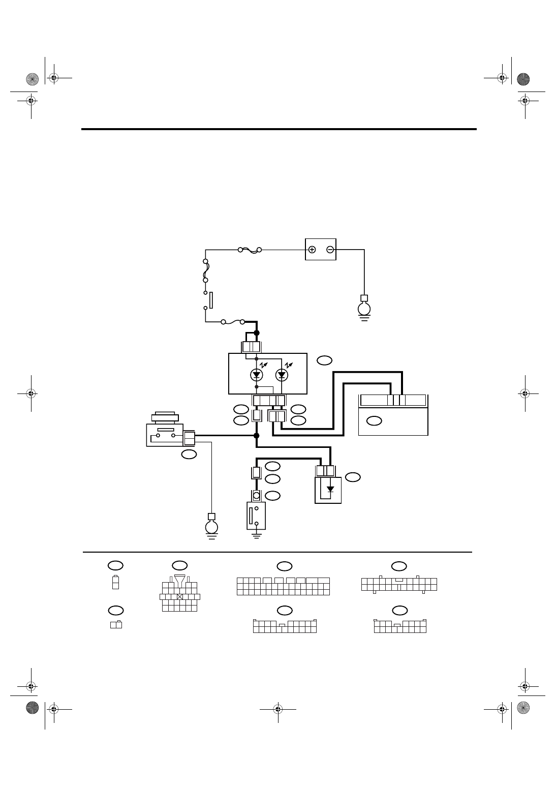
D: ABS WARNING LIGHT DOES NOT GO OFF
DETECTING CONDITION:
• Defective combination meter
• Open circuit of harness
TROUBLE SYMPTOM:
When starting the engine, the ABS warning light is kept ON.
WIRING DIAGRAM:
• LHD model
B310
i1
B16
1
2
B38
E
MAIN SBF
SBF-6
E
No.5
B16
B97
R1
R4
A3
A4
5
1
2
1
2
B229
1 2
3 4
5 6 7 8 9 10
16
11
15
14
13
12
17
19
18
23
25
24
20
22
21
26
28
27
i10
2
1
3 4
6 7 8 9 10
22
21
20
19
18
17
16
15
14
13
12
11
5
1 2 3 4
5 6 7 8 9
10 11 12 13 14 15 16 17 18 19 20
B229
1 2
A:
BATTERY
IGNITION
SWITCH
BRAKE FLUID
LEVEL SWITCH
PARKING
BRAKE
SWITCH
BRAKE
WARNING
LIGHT
ABS
WARNING
LIGHT
20
35
B310
B38
i3
i10
A:
VDCCM & H/U
A7
1 2 3 4
11 12 13 14
27 28 29 30
15 16 17 18
31 32 33 34
19 20 21 22
35 36 37 38
23 24 25 26
39 40 41 42
5
6
7
8
9
10
20
9
16
B36
i1
A8
A5
B97
1 2 3
4 5 6 7
8 9 10 11 12 13 14 15 16
VDC00298

VDC(diag)-32
VEHICLE DYNAMICS CONTROL (VDC) (DIAGNOSTICS)
Warning Light Illumination Pattern
• RHD model
B310
i1
B16
1
2
B97
E
MAIN SBF
SBF-6
E
No.5
B16
B97
R1
R4
A3
A4
5
A8
16
1
2
1
2
B229
1 2
3 4
5 6 7 8 9 10
16
11
15
14
13
12
17
19
18
23
25
24
20
22
21
26
28
27
i10
2
1
3 4
6 7 8 9 10
22
21
20
19
18
17
16
15
14
13
12
11
5
1 2 3 4
5 6 7 8 9
10 11 12 13 14 15 16 17 18 19 20
B229
1 2
A:
BATTERY
IGNITION
SWITCH
BRAKE FLUID
LEVEL SWITCH
PARKING
BRAKE
SWITCH
BRAKE
WARNING
LIGHT
ABS
WARNING
LIGHT
20
35
B310
B36
i1
i10
A:
VDCCM & H/U
A8
A5
16
3
A7
4
1 2 3 4
11 12 13 14
27 28 29 30
15 16 17 18
31 32 33 34
19 20 21 22
35 36 37 38
23 24 25 26
39 40 41 42
5
6
7
8
9
10
VDC00318
Нет комментариевНе стесняйтесь поделиться с нами вашим ценным мнением.
Текст