Subaru Legacy (2005 year). Service manual — part 718
RS-17
REAR SUSPENSION
Rear Shock Absorber
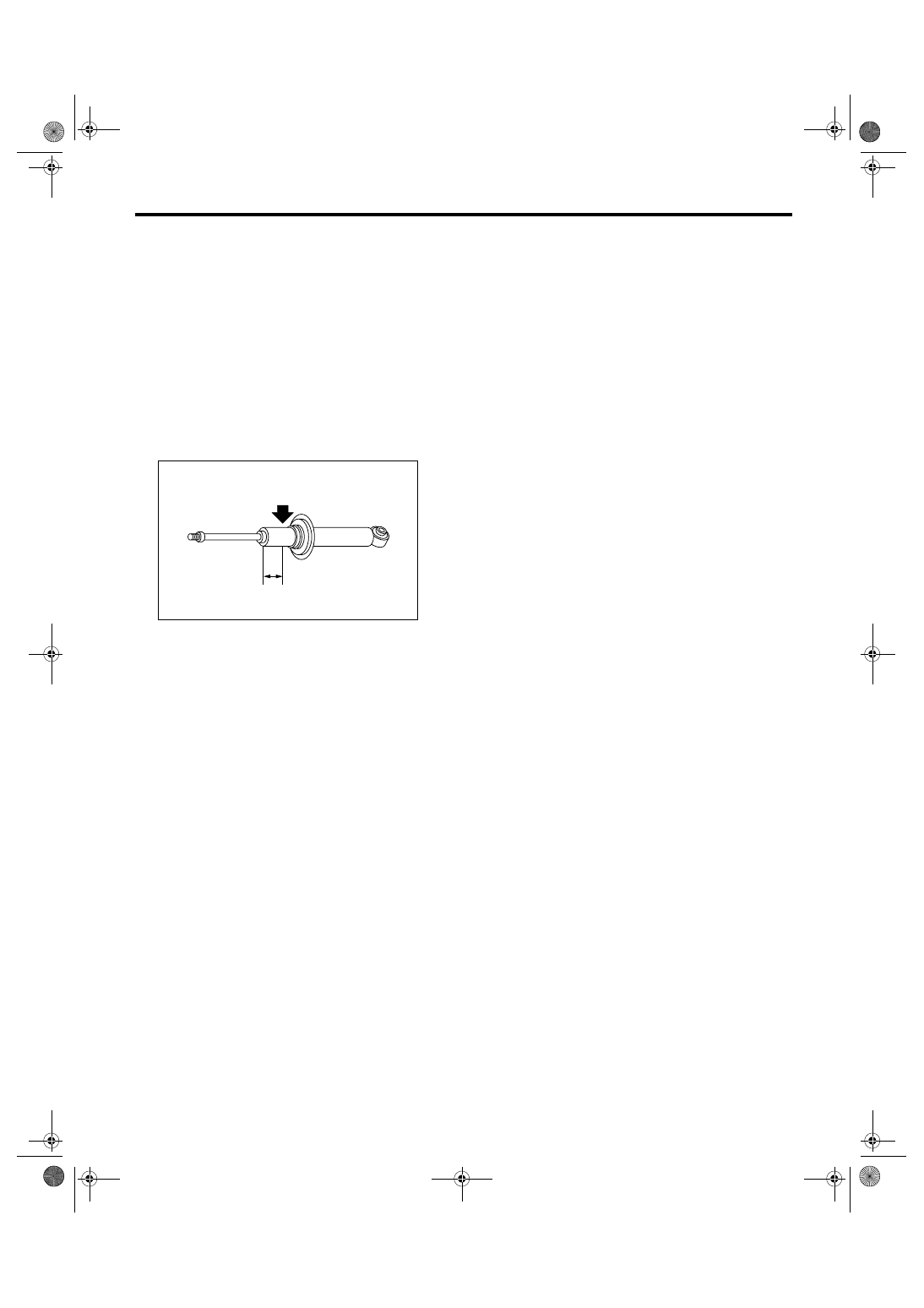
F: DISPOSAL
CAUTION:
• Before handling the shock absorbers, be
sure to wear goggles to protect eyes from gas,
oil and cutting powder.
• Do not disassemble the shock absorber or
place it into a fire.
• Drill a hole into shock absorbers in case of
discarding shock absorbers filled with gas.
1) Place the shock absorber on a level surface with
the piston rod fully expanded.
2) Make a hole into the specified position 30 mm
(1.18 in) deep using a drill with 2 to 3 mm (0.08 to
0.12 in) diameter.
(1) 40 mm (1.57 in)
RS-00135
(1)
RS-18
REAR SUSPENSION
Front Link
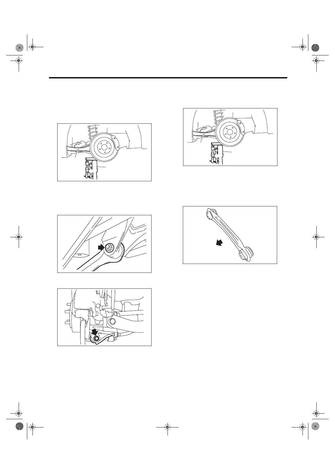
7. Front Link
A: REMOVAL
1) Lift-up the vehicle, and then remove the rear
wheels.
2) Support the rear arm horizontally using trans-
mission jack.
3) Remove the bolt which secure front link to sub
frame.
4) Remove the bolt which secure front link to rear
arm, and then remove the front link.
B: INSTALLATION
1) Support the rear arm horizontally using trans-
mission jack.
2) Using new self-locking nuts, install the front link.
CAUTION:
Install the front link with the protrusion side
faced to the front side of vehicle.
NOTE:
Inspect the wheel alignment and adjust it if neces-
sary.
Tightening torque:
57 N
⋅
m (5.8 kgf-m, 42 ft-lb)
C: INSPECTION
Visually check the front link for damage and defor-
mation.
(1) Rear arm
(2) Transmission jack
RS-00052
(1)
(2)
RS-00072
RS-00073
(1) Rear arm
(2) Transmission jack
(1) Front
RS-00052
(1)
(2)
RS-00075
(1)
RS-19
REAR SUSPENSION
Rear Link
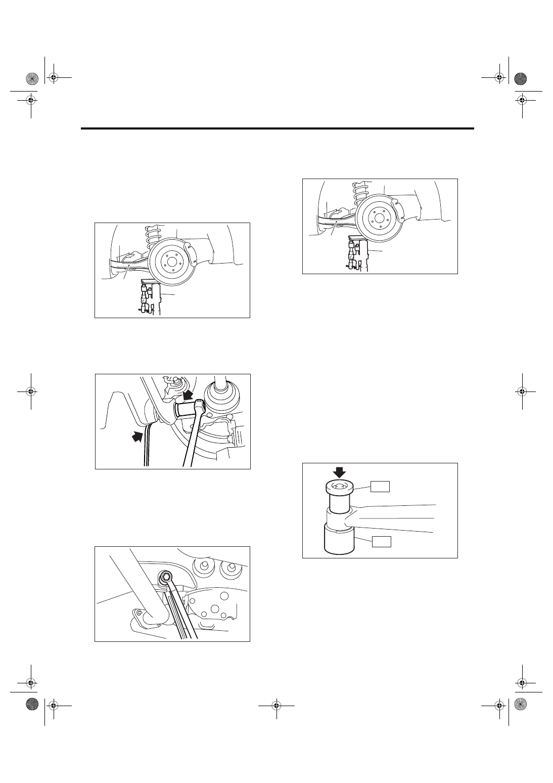
8. Rear Link
A: REMOVAL
1) Lift-up the vehicle, and then remove the rear
wheels.
2) Remove the rear stabilizer. <Ref. to RS-9, RE-
MOVAL, Rear Stabilizer.>
3) Support the rear arm horizontally using trans-
mission jack.
4) Remove the bolts which secure rear link to rear
arm.
5) Put alignment marks on the rear link adjusting
bolt and sub frame.
6) Remove the bolt which secure rear link to sub
frame, and then remove the rear link.
CAUTION:
Loosen the nut with the bolt head secured
when loosening the adjusting bolt.
B: INSTALLATION
1) Support the rear arm horizontally using trans-
mission jack.
2) Using new self-locking nuts, install the rear link.
NOTE:
• Tighten the self-locking nut with the bolt head se-
cured when installing the adjusting bolt.
• Inspect the wheel alignment and adjust it if nec-
essary.
Tightening torque:
Rear link to Sub frame
120 N
⋅
m (12.2 kgf-m, 89 ft-lb)
Rear link to Rear arm
57 N
⋅
m (5.8 kgf-m, 42 ft-lb)
C: DISASSEMBLY
Using the ST A and ST B, press the bushing out of
place.
ST A
20099AE000 INSTALLER & REMOVER
ST B
20099AE000 INSTALLER & REMOVER
(1) Rear arm
(2) Transmission jack
RS-00052
(1)
(2)
RS-00080
RS-00081
(1) Rear arm
(2) Transmission jack
RS-00052
(1)
(2)
RS-00083
ST-A
ST-B
RS-20
REAR SUSPENSION
Rear Link
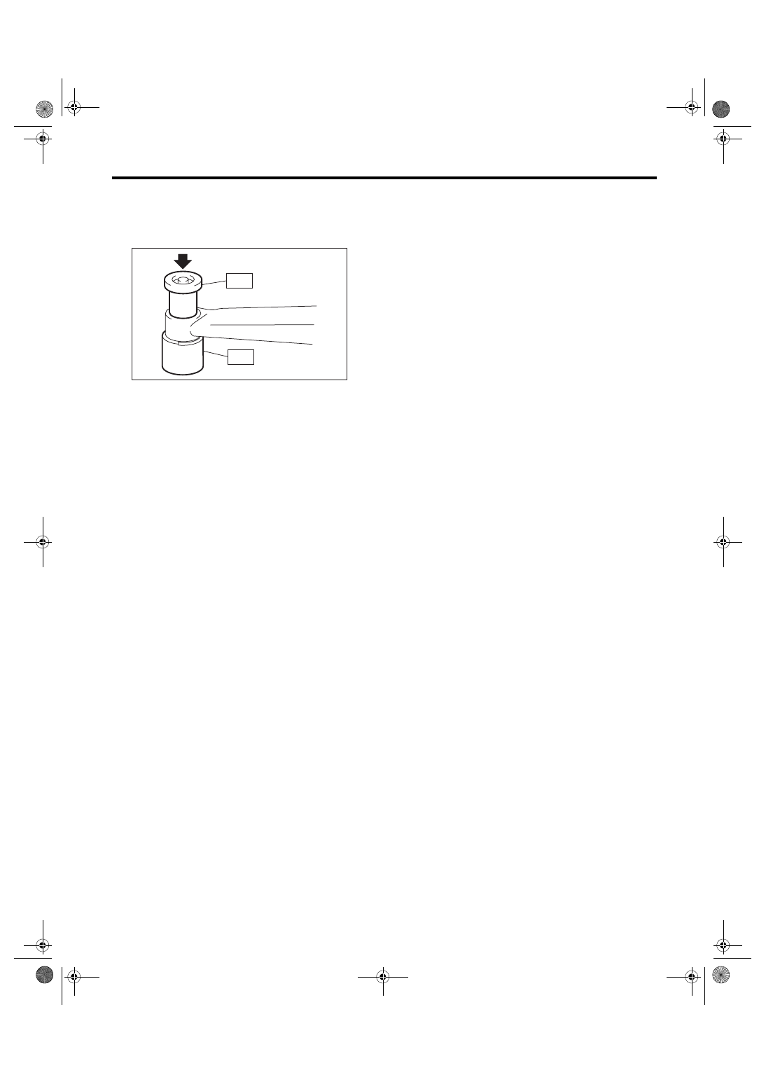
D: ASSEMBLY
Using the ST A and ST B, press-fit the bushing.
ST A
20099AE000 INSTALLER & REMOVER
ST B
20099AE000 INSTALLER & REMOVER
E: INSPECTION
Visually check the rear link for damage and defor-
mation.
RS-00083
ST-A
ST-B
Нет комментариевНе стесняйтесь поделиться с нами вашим ценным мнением.
Текст