Subaru Legacy (2005 year). Service manual — part 716
RS-9
REAR SUSPENSION
Rear Stabilizer
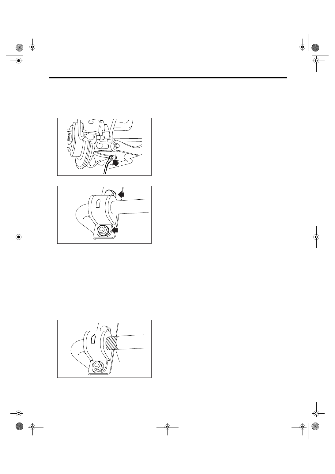
3. Rear Stabilizer
A: REMOVAL
1) Lift-up the vehicle, and then remove the rear
wheels.
2) Remove the stabilizer link.
3) Remove the stabilizer bracket.
B: INSTALLATION
1) Install in the reverse order of removal.
NOTE:
• Use a new self-locking nut.
• Ensure the stabilizer bushing and stabilizer have
the same identification colors.
• To install the stabilizer bushing, align the paint
mark end of stabilizer to the end of stabilizer bush-
ing.
• Stabilizer bracket has an orientation, so install it
with the arrow mark faced to the upper side of ve-
hicle.
2) Always tighten the stabilizer bushing in the state
that wheels are in full contact with the ground and
the vehicle is curb weight.
Tightening torque:
Stabilizer link
44 N
⋅
m (4.5 kgf-m, 32.5 ft-lb)
Stabilizer bracket
40 N
⋅
m (4.1 kgf-m, 30 ft-lb)
C: INSPECTION
1) Check the bushing for crack, fatigue and dam-
age.
2) Check the stabilizer link for damage.
(1) Paint mark
RS-00038
RS-00116
RS-00117
(1)
RS-10
REAR SUSPENSION
Rear Arm
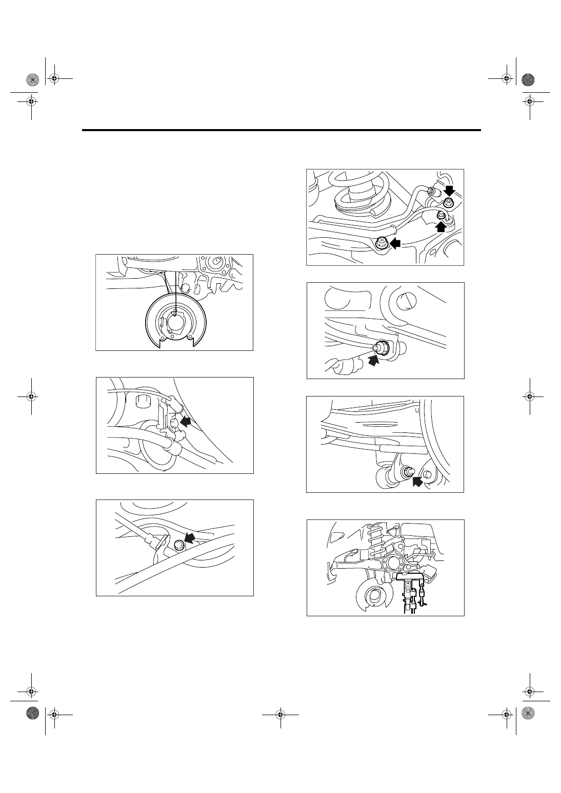
4. Rear Arm
A: REMOVAL
1) Lift-up the vehicle, and then remove the rear
wheels.
2) Remove the sub frame support arm.
<Ref. to RS-21, REMOVAL, Sub Frame Support
Arm.>
3) Remove the bearing unit.
<Ref. to DS-19, REMOVAL, Rear Hub Unit Bear-
ing.>
4) Hang the back plate from sub frame.
5) Remove the bolt which secure parking brake ca-
ble clamp to rear arm bracket.
6) Remove the bolt which hold brake hose bracket
and ABS wheel speed sensor bracket to rear arm.
7) Remove the bolts which secure brake hose
bracket to rear arm. Remove the bolts which se-
cure ABS wheel speed sensor to rear arm.
8) Remove the stabilizer link from rear arm.
9) Remove the shock absorber from rear arm.
10) Support the rear arm horizontally using trans-
mission jack.
RS-00043
RS-00040
RS-00041
RS-00124
RS-00044
RS-00045
RS-00046
RS-11
REAR SUSPENSION
Rear Arm
11) Remove the nuts which hold rear arm to brack-
et. Remove the rear arm bracket.
12) Loosen the nut which hold front link to rear arm.
13) Loosen the nut which hold rear link to rear arm.
14) Loosen the nut which hold upper link to rear
arm.
15) Remove the bolt which secure rear arm to the
link, and then remove the rear arm.
B: INSTALLATION
NOTE:
Use a new bolt and self-locking nut. For the parts
which are not reusable, refer to “COMPONENT”.
<Ref. to RS-3, REAR SUSPENSION, COMPO-
NENT, General Description.>
1) Support the rear arm using transmission jack.
2) Install the rear arm and temporarily tighten the
bolts which hold rear arm to the link.
3) Install the bearing unit.
<Ref. to DS-20, INSTALLATION, Rear Hub Unit
Bearing.>
4) Install the bolts which secure ABS wheel speed
sensor to rear arm.
5) Install the bolts which secure brake hose to rear
arm.
6) Install the bolts which secure parking brake ca-
ble clamp to rear arm bracket.
7) Set the jack which is originally equipped to the
vehicle under the upside down situation, and place
the jack between rear link and sub frame. Align the
installing position of rear shock absorber and rear
arm by adjusting the jack position, temporarily tight-
en the bolt and nut.
CAUTION:
Protect the rear link and sub frame from scratch
in the way of putting a cloth between the jack
and mating portion.
RS-00118
RS-00048
RS-00049
RS-00050
RS-00051
RS-12
REAR SUSPENSION
Rear Arm
8) Support the rear arm horizontally using trans-
mission jack.
9) Tighten the nuts and bolts which hold rear arm,
front link, rear link, upper link and shock absorber.
NOTE:
Always tighten the bushing in the state that wheels
are in full contact with the ground and the vehicle is
curb weight.
10) Install the sub frame support arm.
NOTE:
Inspect the wheel alignment and adjust it if neces-
sary.
Tightening torque:
Refer to “COMPONENT” of “General Descrip-
tion” for tightening torque. <Ref. to RS-3,
REAR SUSPENSION, COMPONENT, General
Description.>
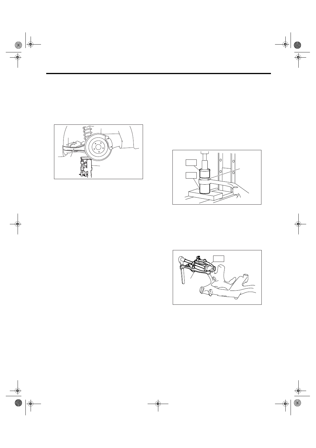
C: DISASSEMBLY
1. FRONT BUSHING
1) Set the ST A with the larger side of its inner di-
ameter turned upward.
2) Set the rear arm with the protruding side of bush-
ing turned upward.
3) Place the ST B on bushing, and push the bush-
ing out.
ST A
20099AE020 INSTALLER & REMOVER
SET
ST B
20099AE020 INSTALLER & REMOVER
SET
2. REAR BUSHING
Using the ST C and bearing puller, press the rear
bushing out of place.
ST C
20099AE040 INSTALLER & REMOVER
SET
(1) Rear arm
(2) Transmission jack
RS-00052
(1)
(2)
(1) Bushing
(1) Bearing puller
RS-00119
(1)
ST-B
ST-A
RS-00054
ST-C
(1)
Нет комментариевНе стесняйтесь поделиться с нами вашим ценным мнением.
Текст