Subaru Legacy (2005 year). Service manual — part 719
RS-21
REAR SUSPENSION
Sub Frame Support Arm
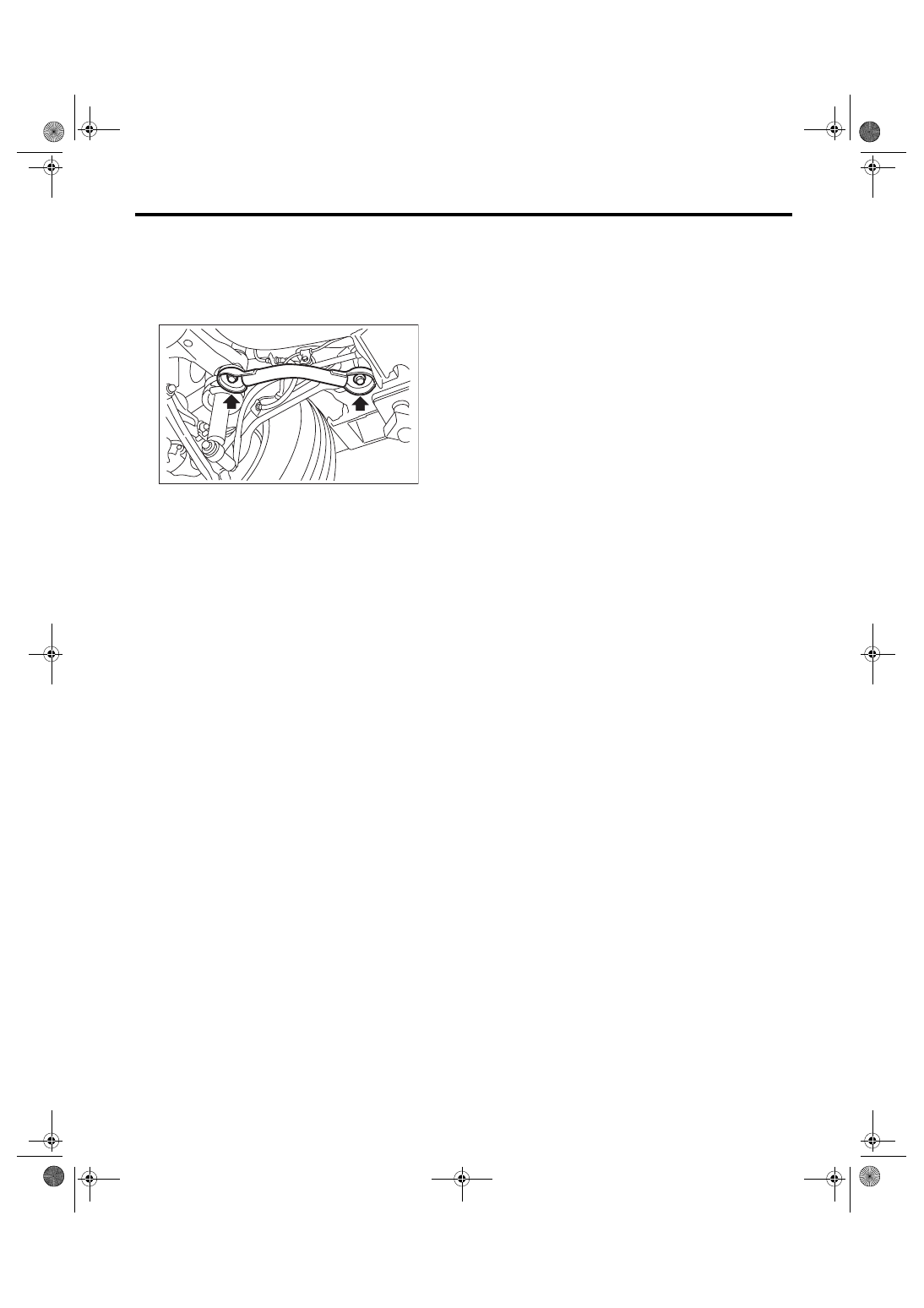
9. Sub Frame Support Arm
A: REMOVAL
1) Lift-up the vehicle, and support the rear sub
frame with support stand.
2) Remove the sub frame support arm.
B: INSTALLATION
Install in the reverse order of removal.
Tightening torque:
Sub frame support arm to Rear arm bracket
80 N
⋅
m (8.2 kgf-m, 59 ft-lb)
Sub frame support arm to Rear sub frame
175 N
⋅
m (17.8 kgf-m, 129 ft-lb)
C: INSPECTION
Visually check the sub frame support arm for dam-
age and deformation.
RS-00088
RS-22
REAR SUSPENSION
Sub Frame Support Plate
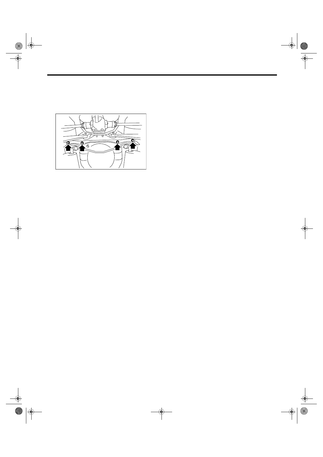
10.Sub Frame Support Plate
A: REMOVAL
1) Lift-up the vehicle, and support the rear sub
frame with support stand.
2) Remove the sub frame support plate.
B: INSTALLATION
Install in the reverse order of removal.
Tightening torque:
Support plate to Sub frame
175 N
⋅
m (17.8 kgf-m, 129 ft-lb)
Support plate to Body
65 N
⋅
m (6.6 kgf-m, 48 ft-lb)
C: INSPECTION
Visually check the support plate for damage.
FU-01134
RS-23
REAR SUSPENSION
Rear Sub Frame
11.Rear Sub Frame
A: REMOVAL
1) Separate the front exhaust pipe and rear ex-
haust pipe.
2) Remove the rear exhaust pipe and muffler.
3) Remove the rear differential.
T-type
<Ref. to DI-29, REMOVAL, Rear Differential (T-
type).>
VA-type
<Ref. to DI-46, REMOVAL, Rear Differential (VA-
type).>
4) Remove the rear stabilizer. <Ref. to RS-9, RE-
MOVAL, Rear Stabilizer.>
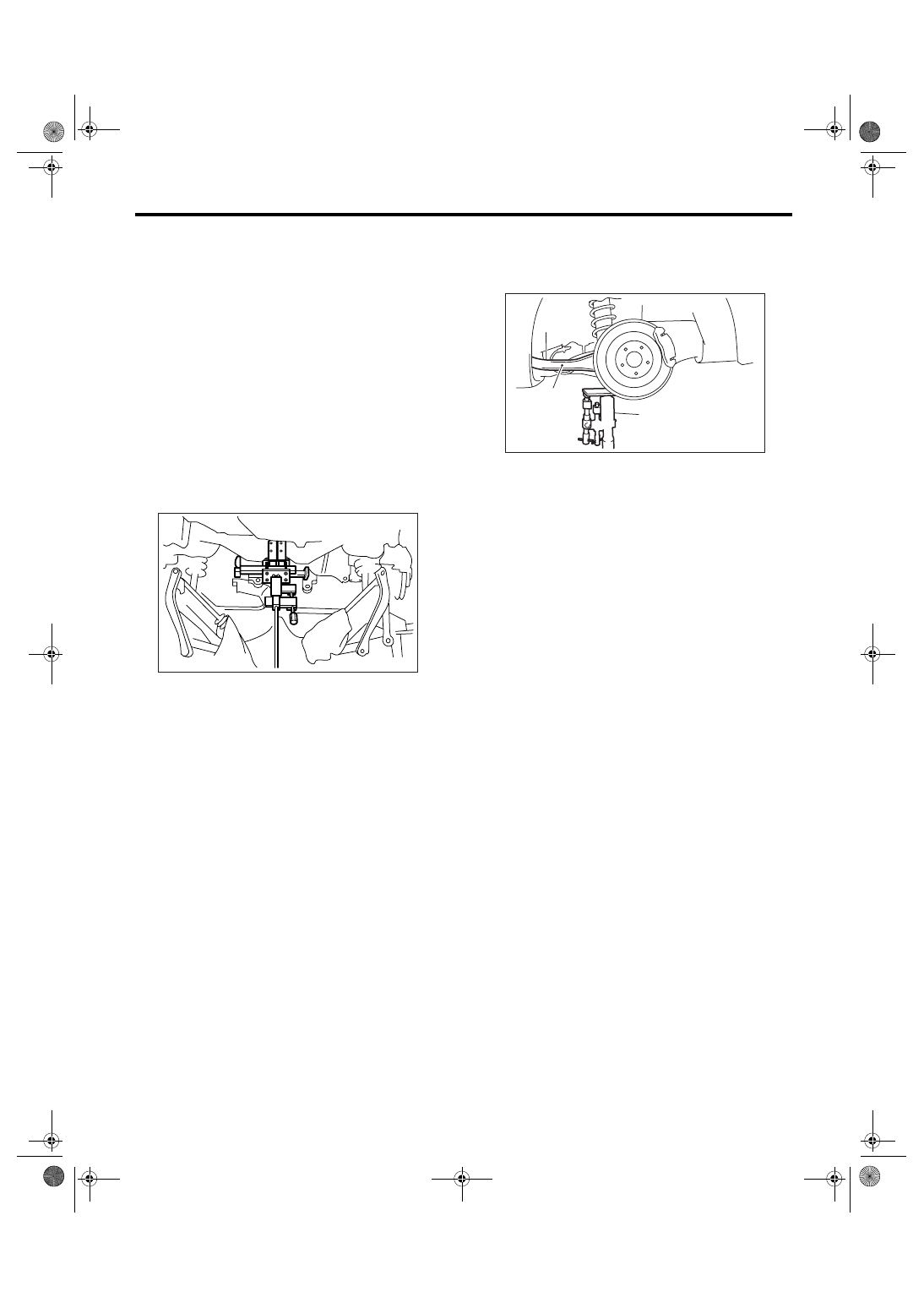
5) Remove the bolts which secure rear shock ab-
sorber to rear arm.
6) Support the sub frame using transmission jack.
7) Remove the front link from sub frame.
<Ref. to RS-18, REMOVAL, Front Link.>
8) Remove the rear link from sub frame.
<Ref. to RS-19, REMOVAL, Rear Link.>
9) Remove the upper link from sub frame.
<Ref. to RS-14, REMOVAL, Upper Link.>
10) Remove the sub frame support arm.
11) After removing the bolt, remove the sub frame
and sub frame support plate from vehicle body.
B: INSTALLATION
1) Install in the reverse order of removal.
2) Follow the procedure below for the rear differen-
tial installation and tightening torque.
T-type
<Ref. to DI-30, INSTALLATION, Rear Differential
(T-type).>
VA-type
<Ref. to DI-47, INSTALLATION, Rear Differential
(VA-type).>
3) Support the rear arm horizontally using trans-
mission jack. Tighten the nuts and bolts which hold
rear arm, front link, rear link, upper link and shock
absorber.
NOTE:
Check the wheel alignment and adjust it if neces-
sary.
C: INSPECTION
Check the removed parts for wear, damage and
crack, and repair or replace them if faulty.
RS-00085
(1) Rear arm
(2) Transmission jack
RS-00052
(1)
(2)
RS-24
REAR SUSPENSION
Helper
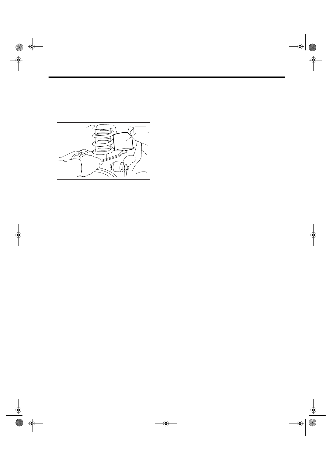
12.Helper
A: REMOVAL
1) Lift-up the vehicle, and then remove the rear
wheels.
2) Remove the helper using ST.
ST
20099AE030
HELPER SOCKET WRENCH
B: INSTALLATION
Install in the reverse order of removal.
Tightening torque:
32 N
⋅
m (3.3 kgf-m, 24 ft-lb)
C: INSPECTION
Check the helper for crack, fatigue and damage.
RS-00087
ST
Нет комментариевНе стесняйтесь поделиться с нами вашим ценным мнением.
Текст